Do you have a question about the IFM KI0054 and is the answer not in the manual?
Explains the meaning of symbols used in the document for clarity.
Illustrates various scenarios where the sensor can be effectively used.
Specifies the required clearance for flush mounting the sensor.
Details the necessary spacing for non-flush sensor mounting.
Outlines spacing requirements when multiple sensors are installed together.
Offers specific instructions for installing the sensor within tanks, with or without medium contact.
Configures the sensor for an empty state, suppressing installation environment interference.
Optimizes sensitivity for specific media, especially aqueous ones.
Adjusts the empty state to ignore deposits, useful in certain tank applications.
Describes how to enable or disable electronic locking of settings to prevent changes.
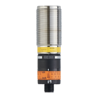
This document provides operating instructions for the ifm KI0054 capacitive sensor, covering its functions, installation, settings, operation, and maintenance.
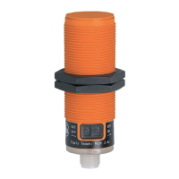
The KI0054 capacitive sensor is designed to monitor the levels of both dry bulk materials and liquids. It is particularly well-suited for applications involving plastic granulates. A key feature of this device is its sensing face, which is rated for temperatures up to 110°C. This allows for direct contact mounting with a sight glass, eliminating the need for an air gap.
The sensor operates by detecting changes in capacitance caused by the presence or absence of a material. This allows it to determine the level of a substance within a tank or container. The device can be configured for both normally open (NO) and normally closed (NC) output states, meaning the output can either close when the tank is full or open when the tank is full, respectively.
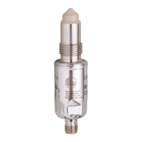
Installation: Proper installation is crucial for the sensor's functionality. The manual provides guidelines for minimum distances during flush and non-flush installations, as well as when installing multiple units to prevent interference. For installations in tanks, the device should be mounted in contact with the medium. For liquids, a mounting adapter (e.g., E11033) is recommended. It is important to avoid mounting the sensor where it will not be in contact with the medium, as this can lead to inaccurate readings. Flush installation of non-flush units can alter sensor properties and potentially cause the sensor to remain permanently switched, leading to a loss of function.
Electrical Connection: The electrical connection must be performed by a qualified electrician, adhering to national and international regulations for electrical equipment installation. Power must be disconnected before connecting the unit. A miniature fuse, as specified in the technical data sheet, should be used. For devices with two-wire technology, the sensor is not short-circuit proof or overload protected, so the safe functioning of the device should be checked after any short circuit. The KI0054 is a class A product to CISPR 11, meaning it may cause radio interference in domestic areas, and users may need to take appropriate measures.
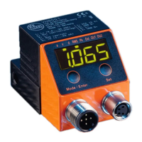
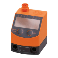
Operating and Display Elements: The sensor features an LED ring (yellow) that indicates the switching output status: LED off means the switching output is disabled, and LED on means it is enabled. Two programming buttons are used for configuration. The sensing face is the part of the device that interacts with the medium to detect its level.
Settings: The KI0054 offers various settings to optimize its performance for different applications:
Basic Teach Empty State: This setting suppresses the installation environment and resets any previously carried out adjustment teach. To perform this, the tank should be empty, with the level at least 20 mm below the device. For normally open (output closes when full) configuration, press the [OUT OFF] button for 2-6 seconds. The LED will flash slowly and then go out. For normally closed (output opens when full) configuration, press the [OUT ON] button for 2-6 seconds. The LED will flash slowly and then remain continuously lit. This basic teach is sufficient for media with low dielectric constants like plastic granulates or oils.
Adjustment Teach Full State: This is necessary for aqueous media to optimize the device's sensitivity. It can be repeated at any time without affecting a basic teach empty state. A basic teach empty state must be performed beforehand. If emptying the tank is not possible, the empty state can be simulated (e.g., by adjusting when not installed or at a higher position). For optimal function, a modified basic teach empty state should be performed when the tank is next emptied. To adjust, fill the tank until the sensing face is covered. For NO, the LED lights; for NC, it goes out. For normally open, press [OUT ON] for at least 6 seconds (LED flashes slowly, then quickly). For normally closed, press [OUT OFF] for at least 6 seconds (LED flashes slowly, then quickly).
Modified Basic Teach Empty State: This is recommended for tanks with deposits, as it helps suppress their influence. It can be repeated at any time and does not affect an adjustment teach full state. The tank should be empty, with the level below the sensing face. The procedure for setting NO or NC is identical to the basic teach empty state, but with a longer button press of at least 6 seconds.
Lock / Unlock: The device can be electronically locked to prevent unintentional settings. The factory setting is unlocked. To lock or unlock, press both [OUT ON] and [OUT OFF] buttons simultaneously for 10 seconds. The LED state will briefly change (either a lit LED goes out briefly, or an unlit LED lights briefly) to acknowledge the action. If the unit does not react, it may already be locked.
Operation: To ensure correct operation, users should check if the unit is functioning as expected and bring about a unit response by taking suitable measures. The yellow LED display indicates the switching output status: LED off means the switching output is disabled, and LED on means it is enabled.
The KI0054 capacitive sensor is designed for maintenance-free operation. However, to ensure its correct functioning and longevity, a few points should be observed:
| Type | KI0054 |
|---|---|
| Connection Type | Cable |
| Protection class | IP67 |
| Bending radius for flexible use | 10 x cable diameter |
| Operating Temperature | -25...70 °C |