Do you have a question about the IFM OID20 Series and is the answer not in the manual?
Explains the meaning of symbols and icons used in the document for clear communication.
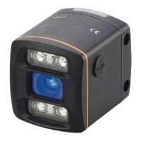
Describes the applications and measuring capabilities of the optical distance sensor.
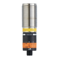
Details the environmental and positioning requirements for proper sensor installation.
Explains how to temporarily switch off the laser for safety and maintenance purposes.
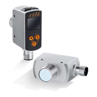
Provides an overview of the unit's IO-Link communication interface and capabilities.
Guides users on where to find necessary IODDs and detailed device information.
Directs users to resources for required IO-Link hardware and software.
This document describes the OID20x optical distance sensor, providing operating instructions and essential information for its safe and effective use.
The OID20x is an optical distance sensor designed to measure distances between 0.03 and 2 meters. It features background suppression up to 20 meters, meaning it can ignore objects beyond a set switch point up to this distance. The sensor provides complementary switching outputs. It utilizes a Class 2 visible laser light for operation. The unit can be configured via an IO-Link interface, allowing direct access to sensor values and parameters. It can also be used without IO-Link, with a preset switch point of 2 meters upon delivery.
| Brand | IFM |
|---|---|
| Model | OID20 Series |
| Category | Accessories |
| Language | English |