Do you have a question about the IFM OGD582 and is the answer not in the manual?
Explains symbols used in the document.
Lists and explains warning symbols used.
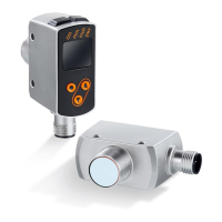
Provides general information about the sensor's functions.
Describes the intended applications and measurement capabilities.
Covers essential steps for installing the sensor.
Instructions to prevent interference from light and dirt.
Guidelines to prevent interference between sensors.
Explains how hysteresis stabilizes output switching based on measured values.
How to align the sensor for moving objects.
Describes defining a window for object recognition based on distance or reflectivity.
How to switch the laser off using a specific input pin.
Explains linking switching outputs using logical operators.
Conditions for installing the unit to ensure proper measurement.
Lists supplied mounting accessories.
Details on how to correctly connect the unit electrically.
Information on operating the unit with an IO-Link master.
Explains the meaning of different display colours.
How display colours are used within the menu system.
Diagram showing the menu structure for configuring the window function.
Diagram showing the menu structure for configuring the hysteresis function.
Detailed explanation of menu parameters and their functions.
Describes the normal operating mode of the sensor.
How to access and view parameters and their values.
How to enter the mode for setting parameters.
General procedure for setting parameter values.
Step-by-step guide to setting a single parameter value.
Instructions for navigating between menu levels.
How to lock and unlock the unit's settings.
Setting switching functions for outputs OUT1 and OUT2.
Details on setting the hysteresis function for output 1.
Explains how hysteresis adapts to signal-to-noise ratio.
Details on setting the hysteresis function for output 2.
How to set switch points for hysteresis functions.
How to configure the window function for output 1.
How to configure the window function for output 2.
Setting switch points for window functions.
Settings for activating or deactivating the display.
How to set background teach for hysteresis.
Teaching switch points for window functions.
Setting hysteresis levels for output 2.
Configuring logic functions for switching outputs.
Setting delay times for switching outputs.
Setting the time for fault suppression.
Procedure to reset all parameters to factory defaults.
General, device-specific, and tool info for IO-Link.
Functions available via IO-Link.
Procedure to check correct unit operation after setup.
Lists possible error indications for output 1 and their causes.
Lists possible error displays for output 2 and their causes.
Guidelines for maintenance, repair, and disposal of the unit.
Technical drawing with dimensions of the sensor.
| Protection class | III |
|---|---|
| Lens material | Glass |
| Operating temperature [°C] | -25...60 |
| Laser protection class | 2 |
| Housing material | Plastic |
| Storage temperature [°C] | -40...70 |
| Protection | IP 67 |