10
6.1 Operation with IO-Link master
The unit is compatible with IO-Link master port class A (type A)�
For operation with IO-Link master port class B (type B) observe the
following:
As a standard, the unit is not compatible with master port class B (type B)�
Pin 2 (OU2) and pin 5 (IN1) are used for manufacturer-specific functions�
That means that the main supply voltage of the unit and the additional
voltage supply (master port class B on pins 2/5) are not electrically isolated�
With the following configurations the unit can be used with master port class B:
• Connect unit and IO-Link master via 3 wires: Connect pins 1, 3 and 4 of the
unit with the IO-Link master (do not connect pins 2 and 5)�
• Connect unit and IO-Link master via 4 wires: Deactivate pin 2 (OU2) via IO-
Link (setting OU2 = "off") and connect pins 1, 2, 3 and 4 of the unit with the
IO-Link master (do not connect pin 5)�
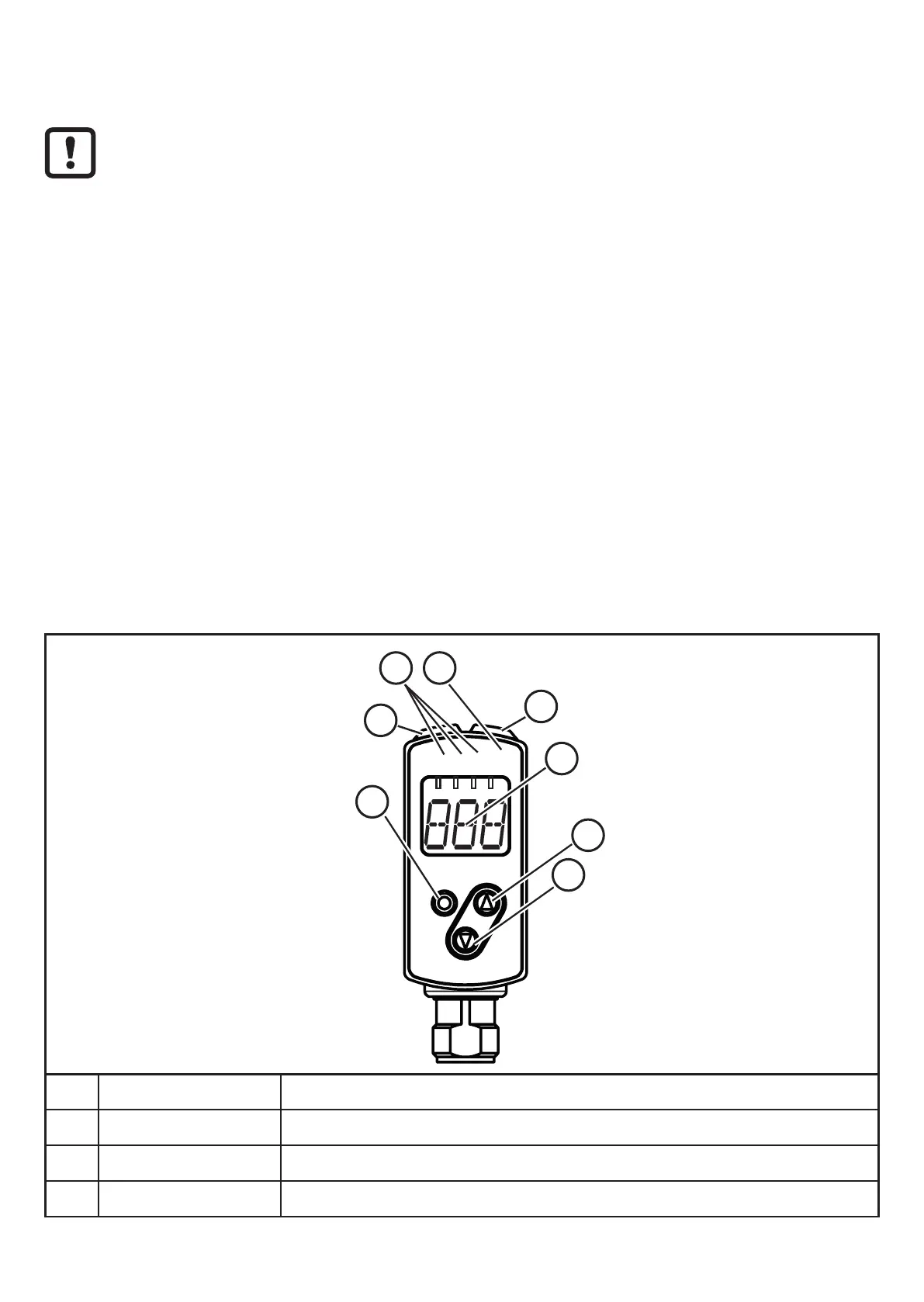
7 Operating and display elements
1
cm
mm
refl
pwr
3
4
5
7
2
6
8
1: 3 LEDs green Active LED = set display unit (cm, mm, refl)
2: 1 LED green Active LED = power
3: 1 LED orange Switching status Out 1
4: 1 LED orange Switching status Out 2