Do you have a question about the IFM O1D120 and is the answer not in the manual?
Explains symbols and warning signs used in the document.
General safety advice for unit setup, intended use, and handling malfunctions.
Describes the sensor's measurement range, background suppression, and display.
Details hysteresis, window, and analogue output functions, plus laser control.
Specifies the measuring range and warns about ambiguous values.
Lists available mounting accessories and their part numbers.
Instructions for connecting the unit by a qualified electrician, ensuring safety.
Details compatibility and configuration for IO-Link master port classes A and B.
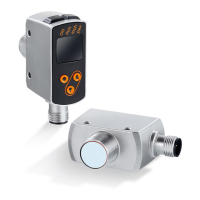
Identifies and explains LEDs, display, and control buttons.
Visual representation of the device's menu hierarchy and parameters.
Explains OUT1 functions, hysteresis, and window settings.
Explains OUT2 functions, hysteresis, window, and analogue settings.
Defines the measured value for 4mA/0V output on OUT2.
Defines the measured value for 20mA/10V output on OUT2.
Configures switch-on and switch-off delays for outputs.
Suppresses errors from short-time saturation or brightness fluctuations.
Configures display update rate and rotation.
Resets all configured parameters to default values.
The normal operating mode where the unit monitors and generates output signals.
Allows viewing of parameters and set values without changing them.
Displays an orientation value for object reflectivity.
Mode for setting parameter values.
General guidelines for parameter adjustment.
Step-by-step guide to setting individual parameter values.
Navigating between different menu levels for advanced settings.
How to lock/unlock the unit to prevent unintentional setting changes.
Sets the unit of measurement (mm, m, inch) for parameters.
Configures display update rate and rotation.
Sets the switching functions for output 1.
Explains how hysteresis maintains stable output switching states.
How to set the specific switch point for OUT1 hysteresis.
Defines a window for object recognition on outputs.
Sets the near and far switch points for OUT1 window function.
Configures OUT2 for hysteresis, window, and analogue outputs.
Configures analogue output scaling for 4-20mA or 0-10V.
Adjusts how often new measurement results are provided.
Sets the sensor's repeatability value.
Provides tables for repeatability and accuracy under different conditions.
Configures switch-on and switch-off delays for outputs.
Suppresses errors from short-time saturation or brightness fluctuations.
Resets all configured parameters to default values.
Shows the sensor's software version.
Overview of IO-Link, device info, and setting tools.
IO-Link specific teach and reflectivity functions.
Table detailing possible causes and their corresponding display and output status.
This document provides operating instructions for the ifm O1D100 and O1D120 optical distance sensors.
The O1D100 and O1D120 are optical distance sensors designed to measure distances between 0.2 and 10 meters. They feature background suppression at distances greater than 10 to 19 meters. The measured value is displayed on a 10-segment display. The sensors can generate two output signals based on configurable output functions.
The device offers several output functions:
[Hno] (normally open): The output switches when the object approaches and reaches the set point (A). It switches back when the object is removed and the reset point (B) is exceeded (B > A).[Hnc] (normally closed): Set and reset points are reversed. The output switches off when the object approaches and switches on when the object is removed.[Fno] (normally open): The output is closed when the measured value is between the "near" switch point [nSPx] and the "far" switch point [FSPx]. It is open otherwise.[Fnc] (normally closed): The output is open when the measured value is between the "near" switch point [nSPx] and the "far" switch point [FSPx]. It is closed otherwise.The sensor also includes an IO-Link communication interface, enabling direct access to sensor values and parameters, and allowing parameter setting during operation. Communication is also possible via a point-to-point connection with a USB adapter cable.
[OFF]).[++] for too much light, [--] for too little light, [nEAr] for object too near, [FAr] for object too far, [Errp] for plausibility error, [LOFF] for laser switched off, [SC1/SC2/SC] for short circuits in switching outputs). These indications also affect the current/voltage output and IO-Link process values.| Brand | IFM |
|---|---|
| Model | O1D120 |
| Category | Accessories |
| Language | English |