EasyManua.ls Logo

IFM OGH - User Manual

IFM OGH
9 pages
Print Icon
To Next Page IconTo Next Page
Loading...
Operating instructions
Diffuse reflection sensor with
background suppression and IO-Link
OGH
80282421 / 00 01 / 2019
UK
Question and Answer IconNeed help?

Do you have a question about the IFM OGH and is the answer not in the manual?

Summary

Preliminary note

Symbols used

Explains symbols used in the manual for instructions and notes.

Safety instructions

Installation

Electrical connection

PNP

Wiring instructions for connecting the sensor's PNP output.

NPN

Wiring instructions for connecting the sensor's NPN output.

Settings

Set via the sensor

Configuration steps performed directly on the sensor unit.

Sensor is to switch when the object is detected

Procedure to set the sensor to trigger when an object is present.

Sensor is not to switch when the object is detected

Procedure to set the sensor to trigger when an object is absent.

Set maximum sensitivity

Adjusts the sensor for optimal detection range and sensitivity.

Programming unsuccessful

Troubleshooting steps for failed programming attempts.

Electronic lock

Instructions for activating and deactivating the electronic lock function.

Set via IO-Link

Guide to configuring sensor parameters using the IO-Link communication.

Set range by means of background and object

Configures the sensor's switching points using object and background targets.

Set range by means of background

Configures the sensor's switching points using only the background target.

Set maximum range

Sets the sensor to detect objects at the furthest possible distance.

Operation

Maintenance, repair, disposal

Overview

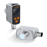
This document provides operating instructions for the OGH diffuse reflection sensor with background suppression and IO-Link.

Function Description

The OGH diffuse reflection sensor is designed to detect objects and materials without physical contact, indicating their presence via a switching signal. This sensor utilizes background suppression, meaning it can differentiate between an object and the background, focusing its detection on the object itself. The integration of IO-Link technology allows for direct access to process and diagnostic data, as well as the ability to set parameters while the unit is in operation. This makes the sensor versatile for various industrial applications where non-contact object detection and advanced configuration capabilities are required.

Important Technical Specifications

The sensor operates within a voltage range of 10-30 V DC. It offers both PNP and NPN output types, with a load capacity of 200 mA. The IO-Link interface enables advanced communication and configuration. For detailed range specifications, users should refer to the type label, which typically indicates performance on a white paper (200 x 200 mm, 90% remission). The unit is designed for robust industrial environments, requiring adherence to national and international regulations for electrical equipment installation.

Usage Features

Installation

The sensor should be aligned to the object to be detected and secured with a bracket. For optimal performance, objects should ideally move transversely to the sensor's lens. If movement occurs in other directions, it is recommended to test the switching function beforehand to ensure reliability. Proper electrical connection by a qualified electrician is crucial, following EN 50178 for voltage supply and disconnecting power before connecting the unit.

Electrical Connection

  • PNP Output:
    • Pin 1: L+ (10-30 V DC)
    • Pin 3: L-
    • Pin 4: Load (PNP, 200 mA) / IO-Link
    • Pin 2: Not connected
  • NPN Output:
    • Pin 1: L+ (10-30 V DC)
    • Pin 3: L-
    • Pin 4: Load (NPN, 200 mA) / IO-Link
    • Pin 2: Not connected

Settings via the Sensor

The sensor can be configured directly using its buttons for various switching behaviors:

  • Sensor to switch when the object is detected:

    1. Position the object in front of the sensor.
    2. Press the [OUTon] button for 2 seconds. The yellow LED will flash, indicating that sensitivity is set to the object.
    3. Remove the object.
    4. Press the [OUToff] button. The yellow LED will turn off, confirming that sensitivity is set without the object, and programming is complete.
  • Sensor not to switch when the object is detected:

    1. Position the object and press [OutOff].
    2. Remove the object and press [OUTon]. Alternatively, settings can be performed without an object first, then with an object.
  • Set maximum sensitivity:

    1. Align the sensor so no light is reflected.
    2. If the sensor is to switch when the object is detected: Press [OUTon] then [OUToff].
    3. If the sensor is not to switch when the object is detected: Press [OUToff] then [OUTon].
  • Programming unsuccessful:

    • Indicated by the LED flashing quickly (8 Hz). This can occur if the measured value difference is too small or if the maximum programming time (15 minutes) is exceeded.
  • Electronic lock:

    • To activate/deactivate, press [OUTon] and [OUToff] simultaneously for 10 seconds. A brief change in the LED status indicates acknowledgment.

The IO-Link interface allows for advanced configuration and access to process and diagnostic data. An IO-Link master is required for operation via this interface. For offline configuration, a PC with suitable IO-Link software and an adapter cable can be used. IODDs (IO Device Descriptions) and detailed information on data structures, diagnostics, and hardware/software requirements are available on www.ifm.com.

  • Set range by means of background and object:

    1. Start the LR DEVICE software.
    2. Align the sensor to the object (Fig. 1).
    3. Select [Teach SP1 TP1] in the software.
    4. Align the sensor to the background (Fig. 2).
    5. Select [Teach SP1 TP2] in the software. The switch point SP1 will be set between the object and the background (Fig. 3). The object can be set first, then the background, or vice versa.
  • Set range by means of background (if object is unavailable):

    1. Start the LR DEVICE software.
    2. Align the sensor to the background (Fig. 4).
    3. Select [Teach Custom - SP1 without target] in the software. The switch point SP1 will be set just in front of the background (Fig. 5). Note that setting the range using both background and object provides the most reliable switching characteristics.
  • Set maximum range:

    1. Start the LR DEVICE software.
    2. Align the sensor to an empty area without any object or background, ensuring no light is reflected back to the sensor.
    3. Select [Teach Custom - SP1 without target] in the software.

Operation

To verify correct operation:

  • The green LED indicates the unit is ready for operation.
  • The yellow LED indicates the switching output is switched.

Maintenance Features

  • Lens Cleaning: Keep the sensor lens free from dirt and debris.
  • Cleaning Agents: Do not use solvents or cleaning agents that could damage the plastic parts of the sensor.
  • Disposal: Dispose of the unit in an environmentally friendly manner, adhering to applicable national regulations.
  • Repairs: Faulty sensors must only be repaired by the manufacturer.

Further technical data and information can be found at www.ifm.com.

IFM OGH Specifications

General IconGeneral
BrandIFM
ModelOGH
CategoryAccessories
LanguageEnglish

Related product manuals