9
UK
5 Installation
5.1 Installation conditions
► Install the unit so that the object to be detected is within the specified
measuring range�
The unambiguity range of the sensor is fixed to 20 m� Objects outside the
measuring range will be suppressed up to the limit of the unambiguity range (20
m)�
Reflecting objects in the direct beam path of the sensor - also in the range
< 20 m – are to be avoided by the customer� Otherwise the measured
values can be ambiguous�
5.2 Mounting accessories
The unit is supplied with mounting accessories�
Pieces Mounting accessories Art. no.
2 metal lock nuts E10027
6 Electrical connection
The unit must be connected by a qualified electrician�
► The national and international regulations for the installation of electrical
equipment must be adhered to�
► Ensure voltage supply to EN 50178, SELV, PELV�
OGD582 and OGD583: cULus, Supply Class 2
► Disconnect power�
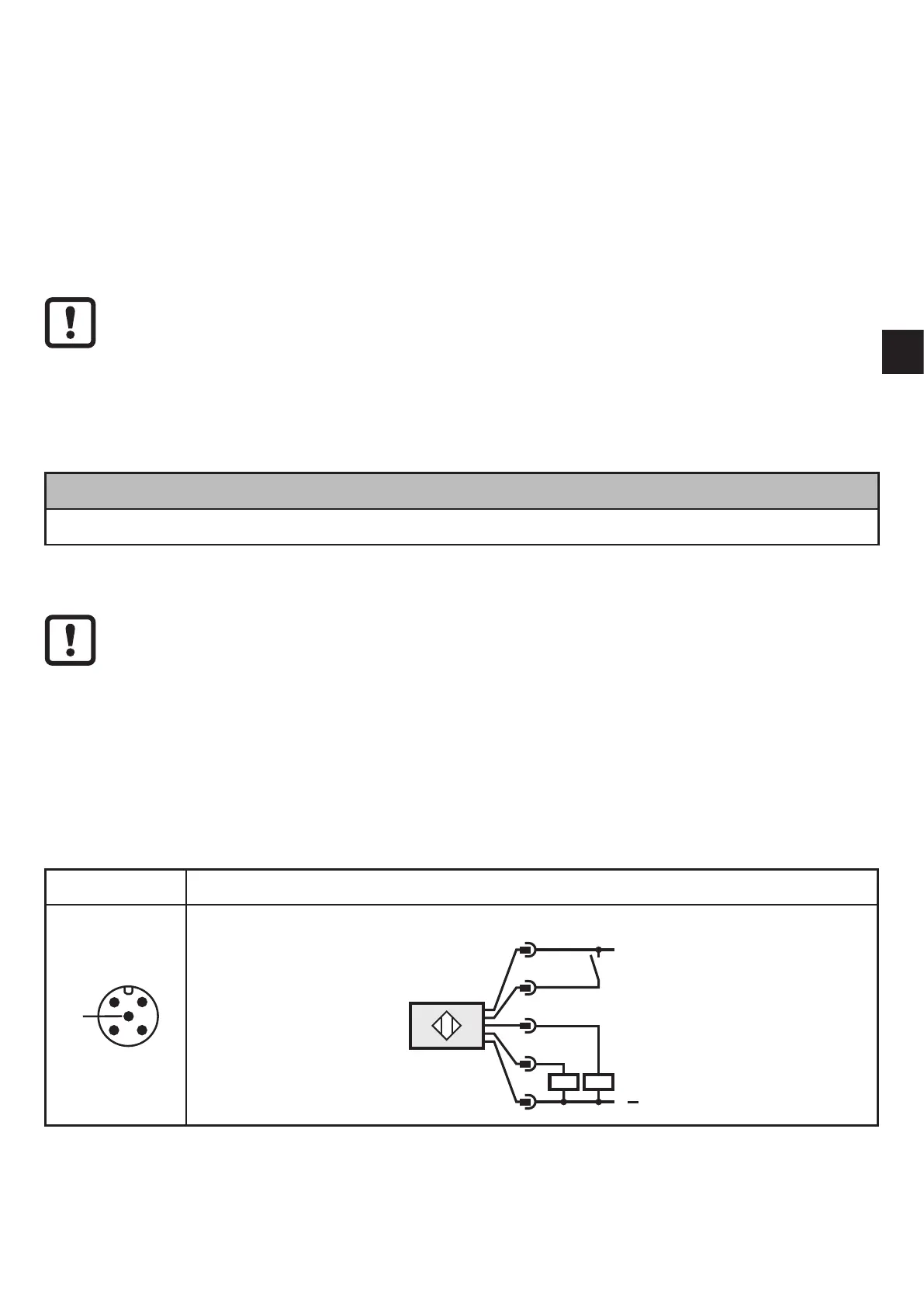
► Connect the unit as follows:
OGD582 / OGD583 PNP
5
L
+
L
5
1
4
3
2
IN
2: Out2
4: Out1
Core colours of ifm sockets:
1 = BN (brown), 2 = WH (white), 3 = BU (blue), 4 = BK (black) 5 = GR (grey)�