6
The light spot should hit the object or the background� Intermediate states
may lead to faulty measured values�
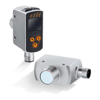
3.2 Applications
• The photoelectric distance sensor measures distances between 8���165 cm and
object reflectivities between 0���999 %�
• It has a background suppression of up to 20 m�
The distance between the sensor and the background must be limited to
max. 20 m. Otherwise measured values can be ambiguous → 5.1.
3.3 Installation instructions
3.3.1 Avoidance of soiling and ambient light
Preferably align photoelectric sensors with the front lens facing downwards or
parallel to the earth's surface�
Background:
• Photoelectric sensors are sensitive to direct radiation of light sources� Everyday
light sources (lamps, sun) radiate from above�
• Photoelectric sensors react sensitively to soiling, as it reduces the excess gain�
Dust deposits can be reduced by downwards or sideways orientation� This
allows for longer cleaning intervals�
Make sure that sensors installed with their front lens facing upwards are not
oriented towards roof windows or ceiling lamps�
3.3.2 Avoidance of mutual interference
Photoelectric sensors should be installed with a sufficient distance between each
other� This particularly applies if the detection range of the two sensors partly
intersects�
Background:
• Both sensors have a detection range� This means that the laser light spot of
a sensor can be received by its neighbouring sensor� This may lead to the
falsification of the measured values and result in incorrect switching�
Mutual interference can be avoided by placing the sensors slightly tilted�
Align the light spots so that they impinge as far away from each other as
possible�