2 - 2 2. NAME AND FUNCTION OF EACH PART
BS-79 BS-79 0212 VOL1 (U) (E)
9 TEMP indicator
On when the internal BS temperature abnormally rises.
Avoid using the BS in a location exposed to direct
sunlight or a badly ventilated environment.
10 HEAD POWER fuse
Prevents overcurrent from running through the camera
head.
11 HEAD POWER indicator
On when power is supplied from the BS to the camera
head.
12 BS MAIN POWER fuse
Prevents overcurrent from running through the BS.
13 BS MAIN POWER indicator
On when the BS main power supply is on.
This indicator normally illuminates green. If the input
voltage falls during DC power operation, this indicator
illuminates red.
14 BS MAIN POWER switch
Turns the BS main power supply and power supplied to
2.2 Inside of the Front
4 AUDIO
+9.5V
+5.5V
+5V
+3.3V
+1.2V
-2V
-5.2V
-9.5V
3 PULSE
4
3
2
1
0
7
6
5
4
3
2
1
0
7
6
5
4
3
2
1
0
7
6
5
C
B
A
9
8
7
6
5
4
3
2
1
0
F
E
D
C
B
A
9
8
7
6
5
4
3
2
1
0
F
E
D
2 MPU&D/A
2 MPU&D/A
1 U/C D/C
3 PULSE
4 AUDIO
4
3
2
1
0
7
6
5
4
3
2
1
0
7
6
5
4
3
2
1
0
7
6
5
C
B
A
9
8
7
6
5
4
3
2
1
0
F
E
D
C
B
A
9
8
7
6
5
4
3
2
1
0
F
E
D
18
19
S1 switch
S2 switch
S3 switch
S7 switch
GENLOCK indicator
HD H PHASE (COARSE) control
HD H PHASE (FINE) control
SD H PHASE (COARSE) control
SD H PHASE (FINE) control
1
2
3
4
5
6
7
8
9
SD SC PHASE (COARSE) control
SD SC PHASE (FINE) control
LOCAL/REMOTE switch
INCOM LEVEL (ENG) control
INCOM LEVEL (PROD) control
PRIVATE/COMMON switch
RCP ON/OFF switch
RBK/RCP connector
DC output indicators
SPARE FUSE holder
10
11
12
13
14
15
16
17
18
19
● PULSE module
● AUDIO module
6 8 1097 11
14 15 16 1713
125
● MPU & D/A module
1 432
U/C D/C
PULSE
AUDIO
MPU&D/A
the camera head on and off.
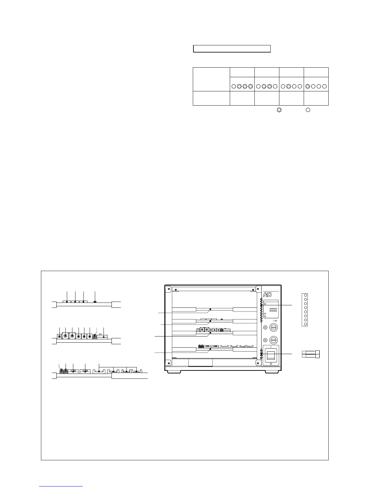
Supplementary information
Red
Yellow
Green
Green
OK
Good
Red
Yellow
Green
Green
ATTENTION
Good
Red
Yellow
Green
Green
WARNING
Noise
produced
Red
Yellow
Green
Green
NG
Noise
Video status
Indicator status
OPTICAL LEVEL
• OK : Good condition
• ATTENTION : The connector can be used, but the cable
connection is becoming dirty and the amount
of light in the receiving section of the connector is a
little insufficient. Clean the optical connectors as soon
as possible. (See Section 5.1.)
• WARNING : Noise begins to appear in video.
The cable connection is dirty and the amount
of light in the receiving section of the connector is
considerably insufficient. Clean the optical connectors
immediately. (See Section 5.1.)
• NG : No video signals can be reproduced.
Clean the optical connectors. (See Section 5.1.)
: On : Off
 Loading...