3. INSTALLATION AND CONNECTION 3 - 5
BS-79 0212 VOL1 (U) (E) BS-79
3.4 Connecting a Control Panel
On the front of the BS-79, you can mount an RBK-79 or RCP-50 as the BS front panel. For how to mount the panel, see Section
3.5, "Mounting a BS Front Panel."
On the back of the BS-79, you can connect an OCP, MCP, CCP, CSU, or RCP-50 to each of the OCP/CCP and MCP/CCP
connectors. You can also connect a device such as an iris remote controller to the REMOTE connector.
When using more than one control panel on split operating modes are available, see Section 4.2.
[Connecting a remote controller]
To connect a device such as an iris remote controller to the REMOTE connector on the back of the BS-79, an RCP-50 must be
mounted as the BS front panel.
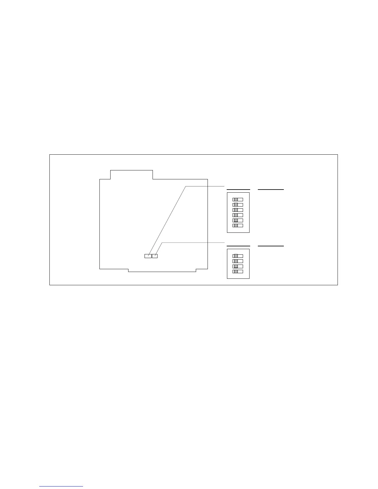
Set the items to be controlled by the remote controller using the RCP CONT BOARD on the RCP-50 (set the corresponding
switches to "ON").
After setting the items, place the REMOTE/LOCAL switch on the front of the RCP-50 to the "REMOTE" position to allow the
remote controller to control the items.
Note: A device such as a iris remote controller is a custom mode device, either made by customer, Ikegami, a third party.
1
2
3
4
5
6
O
N
S3 SW No.
Function
1
2
3
4
5
6
M. PED
IRIS
R BLACK
G BLACK
B BLACK
R GAIN
S3 S4
(LOCAL/REMOTE switch)
1
2
3
4
O
N
S4 SW No.
Function
1
2
3
4
G GAIN
B GAIN
AUTO IRIS
(SPARE)
RCP CONT BOARD