3 - 16 3. INSTALLATION AND CONNECTION
BS-79 BS-79 0212 VOL1 (U) (E)
• When you want to use one external line, use the ENGR line.
• Set the INCOM module switches according to the intercom system to be used.
S2, 3, 5, 6
(4W <-> RTS)
S1, 4
(DUMMY ON <-> OFF)
4W position4W
ON position
RTS positionRTS
OFF position
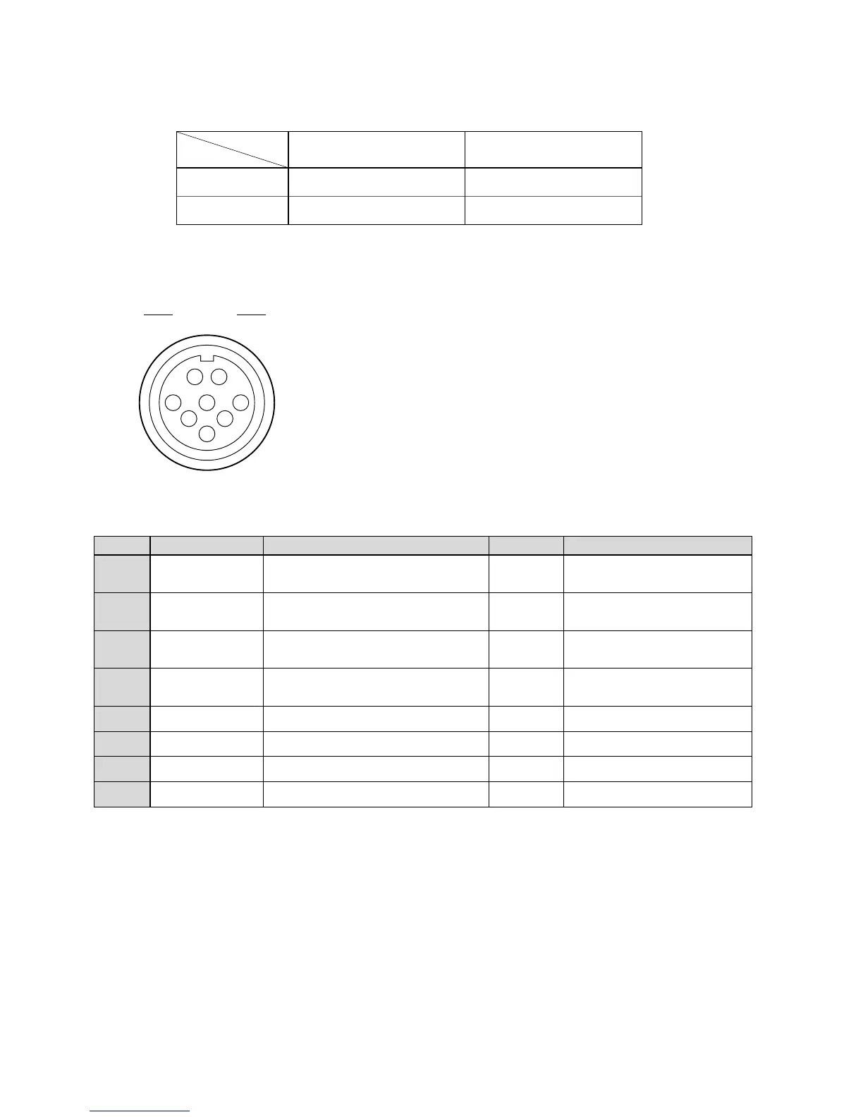
[MCP/CCP and OCP/CCP connectors]
A
B
C
D
E
F
G
H
HED (+)
HED (-)
HEC (+)
HEC (-)
A + 12 V
A + 12 V RET
INC BS-CP
INC CP-BS
Digital data from the camera head to the control
panel (+)
Digital data from the camera head to the control
panel (-)
Digital data from the control panel to the camera
head (+)
Digital data from the control panel to the camera
head (-)
+12 VDC power supplied to the control panel
Ground for +12 VDC power
Intercom output to the control panel
Intercom input from the control panel
OUT
OUT
IN
IN
OUT
RET
OUT
IN
These connectors are used to connect a control panel.
BS side : PRC05-RB8F (Tajimi)
Cable side : PRC05-PB8M (8-pin male plug)
or equivalent
Insertion side
Pin Number
Name Function Direction External Interface
Receptacle
A
B
C
D
E
F
G
H
 Loading...