4. CONNECTION
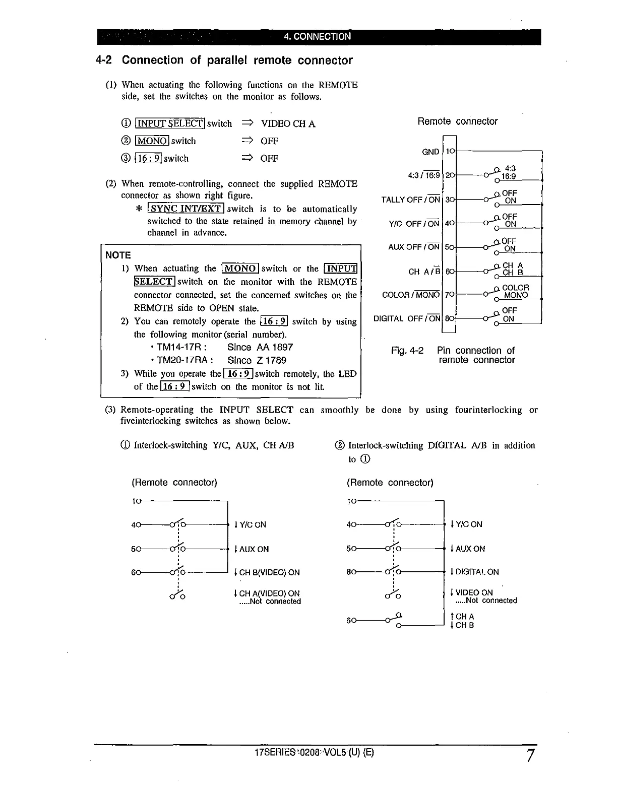
4-2 Connection of parallel remote connector
(I) When actuating the following functions on the REMOTE
side, set the switches on the monitor as follows.
CD l INPUT SELECT I switch
⇒
VIDEO CH A
@ lMONOlswitch
®~switch
⇒
OFF
⇒
OFF
(2) When remote-controlling, connect the supplied REMOTE
connector as shown right figure.
NOTE
* I SYNC INT/EXT I switch is to be automatically
switched to the state retained in memory channel by
channel in advance.
Remote connector
GND
4:3
4:3/ 16:9
16:9
OFF
TALLYOFF/ON 3
ON
OFF
Y/C OFF /ON 4
ON
AUX OFF /ON 6
OFF
ON
CH A/B
CH A
CH B
1) When actuating the )MONO I switch or the lINPU'I1
SELECT I switch on the monitor with the REMOTE
connector connected, set the concerned switches on the
REMOTE side to OPEN state.
COLOR
COLOR / MONO 7 MONO
2) You can remotely operate the l 16 : 9 I switch by using
the following monitor (serial number).
• TM14-17R: Since AA 1897
• TM20-17RA : Since Z 1789
3) While you operate the l 16 : 9 l switch remotely, the LED
of the l 16 : 9 I switch on the monitor is not lit.
OFF
DIGITAL OFF/ ON
ON
Fig. 4-2 Pin connection of
remote connector
(3) Remote-operating the INPUT SELECT can smoothly be done by using fourinterlocking or
fiveinterlocking switches as shown below.
CD Interlock-switching Y/C, AUX, CH NB
(Remote connector)
4o-----------o'f.,._ __ _. I Y/C ON
5o---------o1c>-----I AUX ON
6o------ofc->----~ I CH B(VIDEO) ON
'
'
ifo
I CH A(VIDEO) ON
..... Not connected
@ Interlock-switching DIGITAL NB in addition
to CD
(Remote connector)
4o-----------o'f>----
➔
I Y/C ON
6o-----------o'(J----
➔
! AUX ON
ao---------of<:J----
➔
l DIGITAL ON
'
'
ifo
60------------0-
n---~
! VIDEO ON
..... Not connected
)CHA
l CH B
17SERIES '0208oVOL5 (U) (E)
7
 Loading...