GB | Operating Instruction
• Check whether the delivery is complete.
• Check the device and the accessories for transportation
damage.
• Keep the packaging safely until the guarantee period
has expired, if possible.
ATTENTION
The device and the packing are not children‘s toys!
Children must not be permitted to play with plastic
bags, lm and small parts. There is a risk of them
being swallowed and danger of suocation!
5. MACHINE ASSEMBLY
IMPORTANT: The Machine is supplied with some of the
components disassembled and the fuel tank empty.
WARNING! Always wear strong work gloves to
handle the cutting devices. Mount the components
very carefully so as not to impair the safety and
eciency of the machine. If in doubt, contact your
dealer.
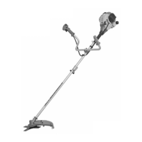
1. COMPLETING THE MACHINE
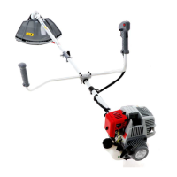
„BIKE HANDLE“ models (Fig. 1)
- Connecting via spring (4), put the below support (5)
onto base (2), located on the drive tube (3).
- Put the handlebar (1) into the seating in the below sup-
port (5), making sure that the controls are on the right.
- Fix the cover (6), fully tightening the knob (8) by hand,
do not forget/missing the washer (7).
The base (2) is already preassembled on the transmis-
sion tube; this position must never be changed.
2. GUIDE SHAFT ASSEMBLY (g. 2)
Put the lower shaft (2) into the shaft coupling and concur-
rently pull out the locking pin (1). Slide the lower shaft in
as far as it will go and let go of the locking pin. The locking
pin must engage into the opening (3) located laterally in
the lower shaft. Of necessary, slightly move the lower shaft
to-and-fro until the locking pin safely locks in place. Then
tighten the y nut (4).
3. FITTING THE GUARDS
WARNING! Each cutting device is provided with
a specic guard. Never use guards other than those
indicated for each cutting device.
• 3 point blade (Fig. 3)
WARNING! Wear protective gloves and t the
blade guard.
- Remove the blade (if tted) as described in paragraph 4.
- The guard (1) is xed to the angle transmission (2) by
two screws (3).
• Cutting line head (Fig. 3)
WARNING! When using the cutting line head the
additional guard, with line cutting knife, must always
be tted.
- Remove the blade (if tted) as described in paragraph 4.
- The guard (1) is xed to the angle transmission (2) by
two screws (3).
- Secure the additional guard (6) using the screw (7).
4. REMOVING AND REFITTING THE CUT-
TING DEVICES
WARNING! Use only original cutting devices or
ones homologated by the Manufacturer.
• 3 point blade (Fig. 4)
WARNING! Wear protective gloves and t the
blade guard.
NOTE: The fastening nut (4) has a left-hand thread
and so must be unscrewed in a clockwise direction and
screwed up anticlockwise.
- Insert the wrench supplied (2) into the specic hole in
the angle transmission (3) and rotate the blade (1) by
hand until the wrench enters the inner hole, blocking
rotation.
- Unscrew the nut (4) clockwise
- Take o the cap (5) and outer ring (6), than remove
the blade (1), taking care not to take o the inner ring
(7) and spacer (8).
When mounting,
- If they were taken o during disassembly, ret the
spacer (8) and the inner ring (7), making sure that the
inner ring’s (7) grooves match perfectly with the angle
transmission.
- Ret the blade (1) and the outer ring (6), with the
protruding edge toward the blade.
- Ret the cap (5) and the nut (4), fully tightening it in an
anticlockwise direction.
- Remove the wrench (2) to restore blade rotation.
• Cutting line head (Fig. 5)
NOTE: The cutting line head has a left-hand thread
and so must be unscrewed in a clockwise direction and
screwed up anticlockwise.
- Insert the wrench supplied (2) into the specic hole in
the angle transmission (3) and rotate the cutting line
head (1) by hand until the wrench enters the inner
hole, blocking rotation.
- Remove the cutting line head (1) unscrewing it in a
clockwise direction.
When mounting:
- If they were taken o during disassembly, ret the
spacer (5), the inner ring-nut (4) and the outer ring
(6),making sure that the inner ring-nut (4) grooves-
match perfectly with the angle transmission.
- Fit the cutting line head (1) screwing it up in an anti-
clockwise direction.
- Remove the wrench (2) to restore shaft rotation.
GB-6

 Loading...