Maschine Assembly
IMPORTANT: The Machine is supplied with some of the
components disassembled and the fuel tank empty.
WARNING! Always wear strong work gloves
to handle the cutting devices. Mount the com-
ponents very carefully so as not to impair
the safety and eciency of the machine. If in
doubt, contact your dealer.
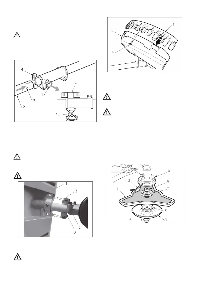
Installing the attachment
Undo the wing screw (4) on the coupling sleeve, pull out
the knob (1) and push the drive axle (2) into the connec-
tor by gently turning it back and forth. The locking knob
(1) must engage fully into its hole (3). Tighten the wing
screw (4).
Fitting the Guards
WARNING! Each cutting device is provided
with a specic guard. Never use guards other
than those indicated for each cutting device.
• 3 point blade
WARNING! Wear protective gloves and t the
blade guard.
- The guard (1) is xed to the angle transmission (2) by
two screws (3).
• Cutting line head
WARNING! When using the cutting line head
the additional guard, with line cutting knife,
must always be tted.
- The guard (1) is xed to the angle transmission (2) by
four screws (3).
- Secure the additional guard (4) using the screw (5).
Removing and retting the cutting devices
WARNING! Use only original cutting devices or
ones homologated by the Manufacturer.
• 3 point blade
WARNING! Wear protective gloves and t the
blade guard.
NOTE: The fastening nut (4) has a left-hand thread
and so must be unscrewed in a clockwise direction and
screwed up anticlockwise.
- Insert the wrench supplied (2) into the specic hole in
the angle transmission (3) and rotate the blade (1) by
hand until the wrench enters the inner hole, blocking
rotation.
- Unscrew the nut (4) clockwise
- Take o the cap (5) and outer ring (6), than remove
the blade (1), taking care not to take o the inner ring
(7) and spacer (8).
When mounting,
- If they were taken o during disassembly, ret the
spacer (8) and the inner ring (7), making sure that the
inner ring’s (7) grooves match perfectly with the angle
transmission.
- Ret the blade (1) and the outer ring (6), with the pro-
truding edge toward the blade.
- Ret the cap (5) and the nut (4), fully tightening it in an
anticlockwise direction.
- Remove the wrench (2) to restore blade rotation.
GB-32