INSTALLATION PROCEDURES
3-16
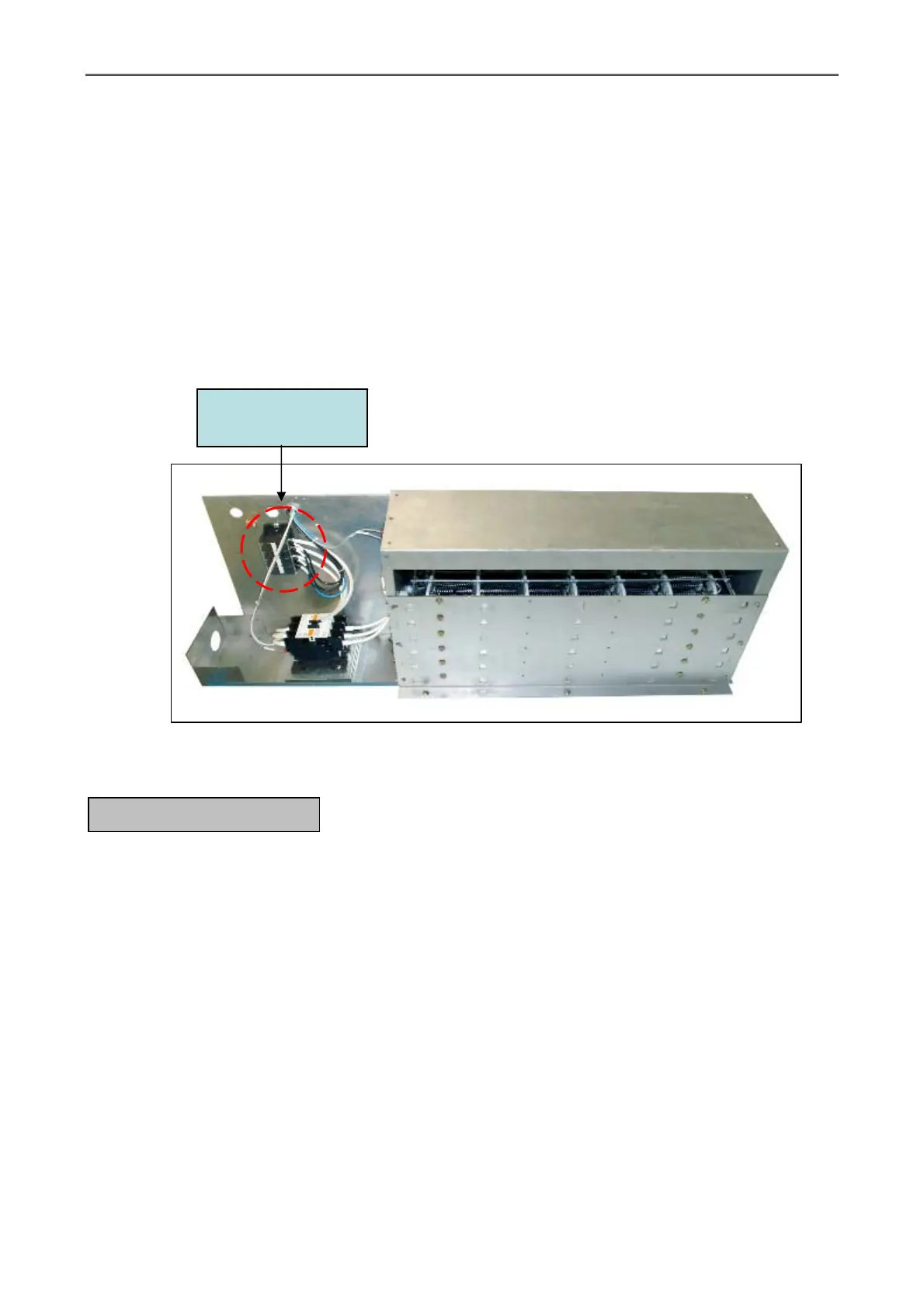
b. Electric Dryers 3 – Phase (3Ø) Hookup
The electrical input connection is made into the electric oven contactor located at the upper
rear of the dryer. Input connection wiring must be sized properly to handle the dryer’s current
draw. This information is printed on the dryer’s data label.
CAUTION: The dryer must be grounded. A ground lug has, been provided in the service box for
this purpose.
NOTE: A separate circuit serving each dryer must be provided.
The only electrical connections to the dryer are the 3 – phase (3Ø) leads (L1, L2, L3, and
sometimes neutral) and ground. Single – phase (1Ø) power for the control circuit is done by the
factory at the contactor (relay), and no other wiring connections are necessary.
Figure.3-15 Electric power connector for electric heater type
It is your responsibility to have all plumbing connections made by a qualified professional to
assure that the gas plumbing installation is adequate and conforms to local and state regulations or
codes. In the absence of such codes, all plumbing connections, material, and workmanship must
conform to the applicable requirements of the National Fuel Gas Code ANSI Z223.1 – LATEST
EDITION, or in Canada, the Canadian Installation Codes CAN/CGA – B149.1 – M91 (Natural
Gas) or CAN/CGA – B149.2 – M91 (L.P. Gas) or LATEST EDITION.
IMPORTANT: Failure to comply with these codes or ordinances, and / or the requirements
stipulated in this manual, can result in personal injury and improper operation of
the dryer.
The dryer and its individual shut – off valve must be disconnected from the gas supply
piping system during any pressure testing of that system at test pressures in excess of 1/2 psig (3.5
kPa). The dryer must be isolated from the gas supply piping system by closing its individual
manual shut – off valve during any pressure testing of the gas supply piping system at test pressures
equal to or less than 1/2 psig (3.5 kPa).
G. GAS INFORMATION
Power connector
(R, S, T)