AC Test Circuit
Figure 2
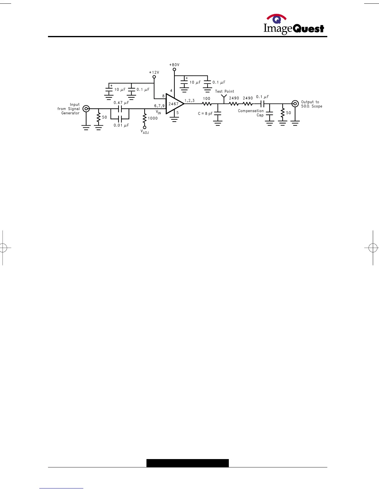
shows a typical test circuit for evaluation of the LM2467. This circuit is designed to allow testing of the LM2467 in a 50Ω
environment without the use of an expensive FET probe. The two 2490Ω resistors form a 200:1 divider with the 50Ω resistor and
the oscilloscope. A test point is included for easy use of an oscilloscope probe.The compensation capacitor is used to
compensate the stray capacitance of the two 2490Ω resistors to achieve flat frequency response.
DS200078-3
Note: 8 pF load includes parasitic capacitance.
FIGURE 2. Test Circuit (One Channel)