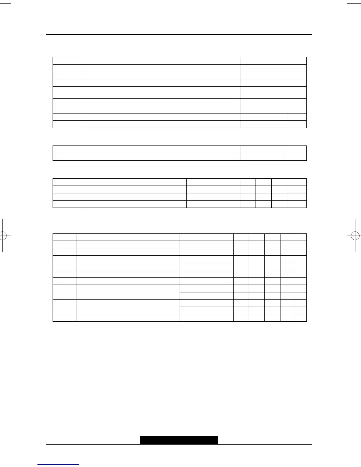
ABSOLUTEMAXIMUMRATINGS AT T
A
=25
o
C
o
C
Symbol Parameter Value Unit
V
S
SupplyVoltage(pin2) 35 V
V
5
,V
6
FlybackPeak Voltage 60 V
V
3
Voltageat Pin3 + V
s
V
1
,V
7
AmplifierInputVoltage + V
s
±0.5
V
I
o
DeflectionOutputCurrent + 1.8 A
I
3
Pin3 DC Currentat V
5
<V
2
100 mA
P
tot
TotalPower Dissipationat T
case
=90 51W
T
stg
,T
j
Storage and JunctionTemperature ±40, +150 5C
9302H 01 TBL
THERMAL DATA
Symbol Parameter Value Unit
R
th (j±c)
ThermalResistance Junction-case Max. 4 5C/W
9302H 02 TBL
ELECTRICALCHARACTERISTICS
(referto the testcircuits, V
S
= 35V, T
amb
=25
o
C unlessotherwise specified)
Symbol Parameter Test Conditions Min. Typ. Max. Unit Fig.
I
2
Pin2 Quiescent Current I
3
=0,I
5
= 0 16 mA 1a
I
6
Pin6 Quiescent Current I
3
=0,I
5
= 0 36 mA 1a
I
1
AmplifierInputBias Current V
1
= 1 V, V
7
=2V ±0.1 ±1mA1a
V
1
= 2 V, V
7
=1V ±0.1 ±1mA1a
V
3L
Pin3 SaturationVoltageto GND
I
3
= 20 mA 1 1.5 V 1c
V
5
QuiescentOutputVoltage
V
s
= 35V, R
a
=39kW 18 V 1d
V
5L
OutputSaturationVoltageto GND I
5
= 1 A 0.9 1.3 V 1c
I
5
= 0.7 A 0.7 1 V 1c
V
5H
OutputSaturationVoltageto Supply ±I
5
= 1 A 1.5 2 V 1b
± I
5
= 0.7 A 1.3 1.8 V 1b
T
j
JunctionTemperatureforThermalShutDown
140 5C
9302H 04 TBL
RECOMMENDED OPERATING CHARACTERISTICS ATT
A
=25
o
C
Symbol Parameter Test Conditions Min. Typ. Max. Unit
V
2M
Recommended SupplyVoltage 25 V
V
2R
OperatingSupplyVoltageRange 15 30 V
I
5PP
DeflectionOutputCurrent 2 App
9302H 03 TBL