--8--
3. Signal Processing and MCU Control
The X-TAL resonates at 12MHz.
When the H and V sync or TTL composite sync are input to MCU, MCU can measures the H and V
frequency to detect the video mode.
MCU has digital to analog converter(DACS) control function like ABL, H-LIN, SBU-SIZE, rotation,
brightness. and MCU can control , Recall, H/V-Size, H/V-Position, Pincushion/Trapezoide,
Top/Botton-Corner, H/V-Linearity, Parallel/Pin Balance, H/V Moire, Color Control, Information,
Language, by I2C BUS Line.
The operation of MCU is shown in the table below.
Stage1
Stage2
Self Test
Theory of Operation
1. Power Supply
The AC line voltage range is from 100V to 240V.
The SMPS has +55V, +7.0V, +14V,+5V, -12V
The conducted noise is filtered by X(CP01, CP04) and Y (CP02, CP03, CP32, CP33, CP09)capacitors
and a common mode line filter (LP01).
The input rectifier (DP01
DP04) converts the AC line voltage into a DC voltage to power the SMPS.
The UC3843B (ICP01) drives the power FET(QP04) according to the PWM signals generated by the R
T
and C
T
(RP07, CP10) connected pin 4 of ICP01.
The ICP01 is an integrated current mode PWM.
It consists of an oscillator, error amplifier, current sense comparator, under voltage lock-out and an
MOSFET drive stage.
The switching frequency is locked to horizontal scan frequency by horizontal flyback pulse.
When the monitor is in Stage2 with no pulsed syncs. QP05 and QP07 is turned off. The total power
consumption must be less than 5W in Stage2.
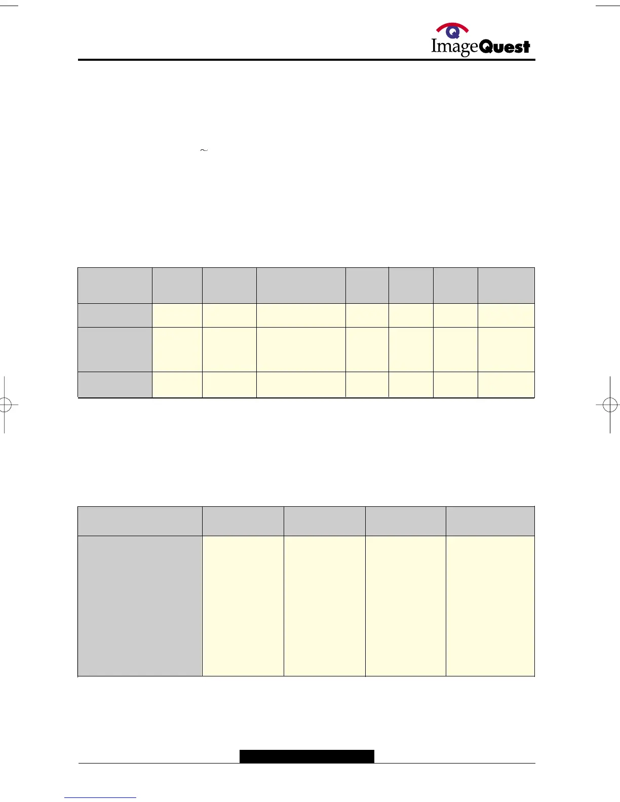
2. DPMS and Self test mode
The power supply supports the DPMS function. Its operation is shown in the table below.
MODE
H-SYNC
V-SYNC
MCU
PIN35
(BRI)
MCU
PIN 10
(Suspend)
Q905
QP07
14V
HEATER
O
X
O
X
X
O
O
X
X
X
CONTROL
0
3.5V
H
L
H
ON
OFF
ON
6.3V
2V
6.3V
14V
0V
14V
H-FREQ
(kHz)
H-LIN1
PIN 30
H-LIN2
PIN 29
H-LIN3
PIN 28
REMARK
31 < H < 34
34 < H < 36
36.0 < H < 41
41.0 < H < 46
46 < H < 52
52 < H < 59
59< H < 62
62.0<H<66
66.0<H<69
L
L
L
L
H
H
H
H
H
L
L
H
H
L
L
H
H
H
L
H
H
H
L
H
L
L
H