18 UDC-5212 and DTD-5225 Digital Time/Date Display Clocks Installation and Operation Manual
Chapter 2: DTD-5225 Series Digital Time/Date Display
Control Modes
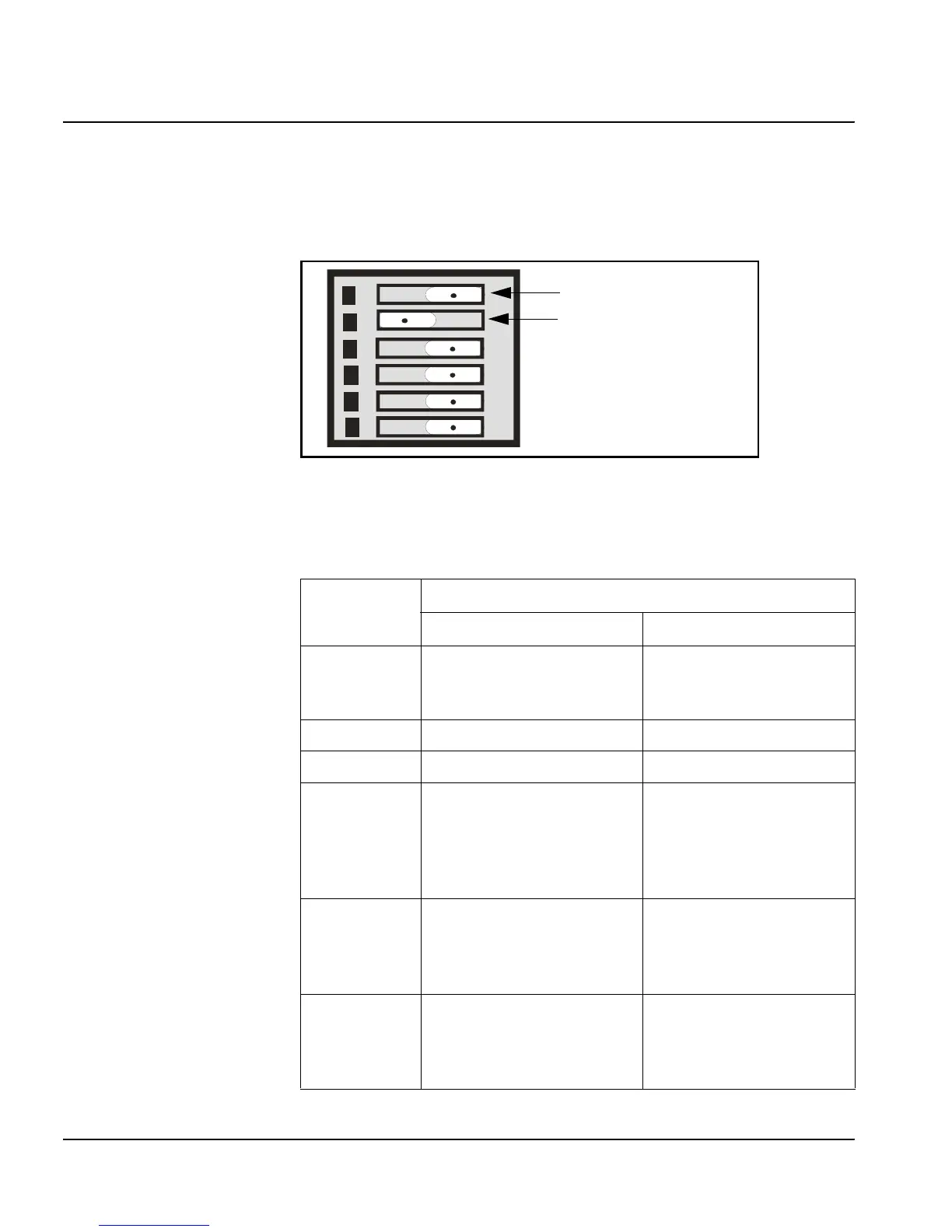
Selection of the clock control modes is achieved with the rear panel DIP
switches. Figure 2-2illustrates the possible two DIP switch states
Figure 2-2. DIP Switch Positions
Table 2-10 lists the Clock Control mode DIP switch options.
Table 2-10. Clock Control Mode DIP switch options
Dip Switch
Switch Postion Options
Left Right
6
Clock
(See “Clock Mode” on page 19)
Timecode
(See “Timecode Reader
Mode” on page 19)
5 SMPTE EBU (Sweep seconds)
4 Internal Line
3 Normal Use offset (MTG-3901,
CSD-3901/3902, or
CSD-5300 required)
(See “Auxiliary Offset” on
page 20)
2 Normal Use secondary reference
(date if code is present)
(See “Secondary Reference
Mode” on page 20)
1
12 Hour (Clock selected);
HH:MM:SS (timecode selected)
DD:MM:YY (date selected)
24 Hour (Clock selected);
MM:SS:FF (timecode
selected);
MM:DD:YY (date selected)
6
5
4
3
2
1
Switch in right postiition
Switch in left postiition
 Loading...