4 UDC-5212 and DTD-5225 Digital Time/Date Display Clocks Installation and Operation Manual
Chapter 1: UDC-5212 Universal Digital Clock
Table 1-2 lists the required rack space for each clock.
Rear Panel
The rear panel is provided with two spring-loaded speaker-type
connectors. Depending on the configuration, these may be used to
accept the serial timecode (SMPTE or EBU) or may be used as the
timecode output terminals. The rear panel also indicates the type of
operation, that is either MASTER or SLAVE. All clocks are shipped
configured for timecode input (slave) operation, unless otherwise
specified when ordering. A standard AC power connector and cord are
also included.
Control Modes
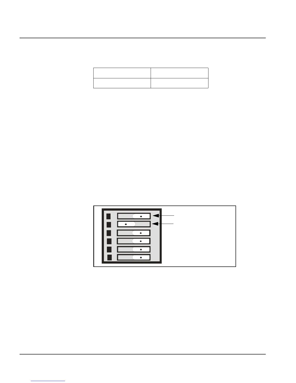
Selection of the clock control modes is achieved with the rear panel DIP
switches. Figure 1-1illustrates the possible two DIP switch states
Figure 1-1. DIP Switch Positions
Table 1-2. Required Space For Rack Mounting UDC-5212
Rack Units Inches
8 14.0
6
5
4
3
2
1
Switch in right postiition
Switch in left postiition
 Loading...