18
3-3
INSTALLERUSER
MAINTENANCE TECHNICIAN
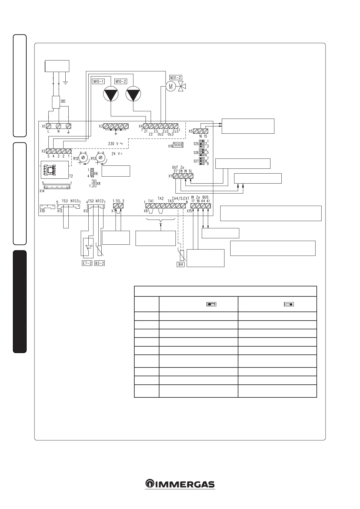
3.3 DIM HLT ERP WIRING DIAGRAM.
e zone control C.A.R.
V2
or Super C.A.R. remote
control must be connected directly to the boiler
and it will control Zone 2, which is pre-set as the
main zone on the manifold set as the Master (see
table above). In the event that two or more zones
are used, the chrono-thermostat must be set with
on-o operation (see instructions in the relative
booklet). The H.T. electric connections con-
trolled by the chrono-thermostat must be free.
Key:
B4 - External probe (optional)
B3-2 - Zone 2 low-temperature ow
probe
E7-2 - Zone 2 low-temperature safety
thermostat
M10-1 - Zone 1 pump
M10-2 - Zone 2 pump
M31-2 - Mixing valve zone 2
R12 - Zone 2 low-temperature ow
regulation trimmer
R13 - Zone 3 low-temperature ow
regulation trimmer
S25 - Board setting selector
S26 - Board setting selector
S27 - Board setting selector
T2 - Zone control unit low-voltage
feeder
On connecting the zone control Room ermostats, it is necessary to eliminate the jumpers present in the zones control unit on terminal board X9.
On connecting the DIM safety thermostat, it is necessary to eliminate the jumper on X7.
ZONE CONTROL UNIT SETTINGS
N°
SWITCH
OFF ON
1 Homogeneous zone control Mixed zone control
2 N° 1 mixed zone (Z2) N° 2 mixed zones (Z2 and Z3)
3 MASTER board SLAVE board
4 Main zone = zone 1 Main zone = zone 2
5 Super C.A.R.: main zone ow control Super C.A.R.: system ow control
6
Mixed zones max. temperature =
50°C
Mixed zones max. temperature = 75°C
7 Normal functioning Multi-zone recognition state
8 Not used Not used
9
Mixed zones minimum temperature
= 25°C
Mixed zones minimum temperature
= 35°C
N.B.: the default settings are highlighted in bold.
Black
Grey
Blue
Blue
Blue
Black
Blue
Brown
Brown
Orange
Red
Brown
Brown
Power supply
230 Vac
50 Hz
ZONES
CONTROL UNIT
Black
Red
Red
Red
Red
CENTRAL HEATING REQUEST INLET
FROM OTHER DIM
ZONES SIGNAL STATE OUTLET
FOR OTHER DIM
CENTRAL HEATING REQUEST
OUTLET TO BOILER
OR OTHER DIM
By connecting the zone control Room ermostats, it is necessary
to eliminate the jumpers in the zones control unit
on terminal board X9.
Connecting the DIM safety thermostat, it is necessary to
eliminate the jumper on X7.
ZONES SIGNAL STATE
INLET FROM BOILER OR
OTHER DIM
BUS IMG CONNECTION
TO BOILER
CONNECTIONS TO ON/
OFF ROOM THERMOSTATS
CONNECTION
TO DIM SAFETY
THERMOSTAT
OFF ON
Y./G.