7
INSTALLERUSER
MAINTENANCE TECHNICIAN
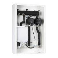
1.4 HYDRAULIC CONNECTION.
Attention: before making the appliance connec-
tions, clean the heating system thoroughly (pipes,
radiators, etc.) with special pickling or de-scaling
products to remove any deposits that could
compromise the correct operation of the device.
A chemical treatment of the thermal system wa-
ter is required, in compliance with the technical
standards in force, in order to protect the system
and the appliance from deposits (e.g., lime scale),
slurry or other hazardous deposits.
e hydraulic connections must be made in a
rational manner using the values as per Fig. 1-2.
IMPORTANT: remove all the protection caps
from the system ow and return pipes before
making the hydraulic connections.
e connections can be made directly using the
female couplings on the distribution manifold
or by inserting system cut-o cocks (optional).
ese cocks are particularly useful for mainte-
nance as they allow you to drain the distribution
manifold separately without having to empty the
entire system.
N.B.: Immergas does not supply the G1” cocks to
be installed in the low-temperature zone.
Check that the expansion vessel in the boiler
allows for the increase in volume of the water
resulting from its central heating without open-
ing the safety valve. If this is not the case, an
expansion vessel with appropriately dimensioned
capacity must be installed on the system.
e DIM is set up for the insertion of the auto-
matic “jolly” vent valve to be mounted on the
manifold. is is recommended for better air
venting inside the system.
If two DIM devices are installed in parallel, two
manual valves must be tted in order to ensure
the correct balance of the hydraulic circuit.
1.5 ELECTRICAL CONNECTION.
e appliance has an IPX5D protection degree;
electrical safety of the appliance is achieved only
when it is connected properly to an ecient
earthing system, as specied by current safety
standards.
Attention: Immergas S.p.A. declines any respon-
sibility for damage or physical injury caused by
failure to connect the boiler to an ecient earth
system or failure to comply with the reference
standards.
Moreover, ensure that the electrical installation
corresponds to the maximum absorbed power
specications as shown on the recessed unit data
plate. e distribution manifold is supplied com-
plete with an “X” type power cable without plug.
e power supply cable must be connected to a
230V ±10% / 50Hz mains supply respecting L-N
polarity and earth connection;
this network
must also have a multi-pole circuit breaker with
class III over-voltage category.
To protect from possible dispersions of DC volt-
age, it is necessary to provide a type A dierential
safety device.
When replacing the power supply cable, contact a
qualied company (e.g. the Immergas Authorised
Aer-Sales Technical Assistance Service).
For the main power supply to the appliance,
never use adapters, multiple sockets or exten-
sion leads.
Important: it is mandatory to prepare two elec-
trical connection lines in order to separate the
power supply of each distribution manifold from
all other low-voltage connections, according to
the standards in force regarding electrical sys-
tems. ese lines must arrive inside the recessed
frame via relevant sheaths or ducts, passing
through the fairlead and the sheath-holder sup-
plied and located on the upper side of the device.
• Connecting the boiler P.C.B. is connection
(low-voltage) ensures the dialogue between
the boiler and the DIM. Make the connections
as indicated in chapter 3, according to your
appliance model.
N.B.: the electrical connection between the
electronic boards must be made using cables
with a minimum section of 0.50 mm
2
and a
maximum section of 2.5 mm
2
; the length of
these connections must not exceed 15 metres.
• Room thermostat connection On - O. e
room thermostats to be connected to the DIM
must have a potential free contact. e On-O
room thermostats relative to the zones must be
connected as indicated in Fig. 3-8 or 3-9.
• Immergas remote control connection.
Connect the remote controls as indicated in
gures 3-11, 3-12 and as specied in the boiler
instruction manual.
• External probe connection (optional). e
external probe controls the ow temperature of
the system and varies the operation mode and
controlled zones depending on its connection
(see par. 3.14).
- e external probe must be connected to
the boiler by connecting the manifold and
the boiler via IMG BUS. (fig. 3-5). The
temperature read by the external probe is
sent to the manifold via bus. e manifold
will then adjust the ow temperature of the
various zones, according to the settings of the
trimmer and area management probe.
- e external probe must be connected to
the manifold by connecting the manifold
and boiler via signal state. is way, it will
be possible to adjust the ow temperature of
the mixed zones. In these conditions, another
probe must be connected to the boiler if it is
necessary to correlate the direct zone ow
with the external temperature (see Fig. 3-6).