28
3-18
INSTALLERUSER
MAINTENANCE TECHNICIAN
3.12 DESCRIPTION OF MAIN
FUNCTIONS.
ree-way valves/anti-block pumps.
The device is supplied with a function that
makes the pumps start (according to the model
installed) at least 1 once every 24 hours in order
to reduce the risk of pump blocking due to pro-
longed inactivity. In the case of the H-LT and
H-2LT versions, the same function also acts on
the mixing valve in order to prevent and avoid
the risk of blocking due to prolonged inactivity.
Post-circulation.
System post-circulation can be performed, con-
trolled by the boiler, in the system zone selected
as the main zone (see installation layout).
Summer DHW/functioning priority.
In the case of DHW or boiler functioning pri-
ority in Summer mode, all active pumps are
deactivated and any mixing valves are closed
(only for L-HT and H-2LT versions). Normal
functioning of the DIM re-starts at the end of
the DHW phase, taking the boiler switch to the
Winter position.
Mixing valve initialisation.
(Only for DIM H-LT and H-2LT).
Every time that the the appliance is powered,
initialisation of the mixing valves is carried
out, closing them for three minutes. is way,
synchronisation is performed between the P.C.B.
and the mixing valve. e transfer of heat energy
to the Low-Temperature zone can only take place
at the end of this initialisation phase.
Anti-freeze.
(Only for DIM H-LT and H-2LT).
e P.C.B. is supplied with a function that pro-
tects the Low-temperature system if the system
water drops below 5°C.
3.13 ZONE MANAGEMENT P.C.B.
e zone control unit can be congured using
the selector switches on the unit (14 Fig. 3-18),
via which you can choose between the following
options:
n° OFF ON
S25
1
Homogeneous
zone control
Mixed zone
control
2
N° 1 mixed zone
(Z2)
N° 2 mixed zones
(Z2 and Z3)
3 Master board Slave board
S26
4
Main zone =
zone 1
Main zone =
zone 2
5
Super CAR: main
zone ow control
Super CAR: sys-
tem ow control
6
Mixed zones max.
temperature =
50°C
Mixed zones max.
temperature =
75°C
S27
7
Normal func-
tioning
Multi-zone recog-
nition state
8 Not used Not used
9
Mixed zones min-
imum tempera-
ture = 25°C
Mixed zones min-
imum tempera-
ture = 35°C
- S26 (5) can only be modified if the Super
C.A.R. remote control can be coupled with the
Superior kW range boilers.
- S26 (6) in the event of the setting with max.
ow temperature of 75°C, the relative safety
thermostat must be replaced with one suitable
for supporting this temperature.
Warnings. Various LEDs are present on the
board to display the functioning status and to
indicate any anomalies.
e LEDs from 1 to 7 (13 Fig. 3-18) identify the
activation of the relative relay:
- LED H1 zone 1 activation (high temperature)
- LED H2 zone 2 activation (low temperature)
- LED H3 zone 3 activation (optional)
- LED H4 mixer opening zone 2 L.T.
- LED H5 mixer opening zone 2 L.T.
- LED H6 mixer opening zone 3 (optional)
- LED H7 mixer closing zone 3 (optional)
e LED H11 signals that the zone management
board is powered.
LEDs 8 and 9 indicate the functioning status of
the board:
Warning H8 H9 H10
CH request presence ON OFF OFF
Disabling of active
zones
ON L OFF OFF
Zone 2 safety ther-
mostat intervention
OFF ON OFF
Zone 2 L.T. probe
fault
OFF ON L OFF
Zone 3 safety ther-
mostat intervention
OFF OFF ON
Zone 3 L.T. probe
fault
OFF OFF ON L
Bus IMG anomaly OFF ON A ON A
IMG communication
present
OFF OFF ON F
Intervention of
safety thermostat
B.T. DIM
OFF ON V OFF
Key:
ON = ON
OFF = OFF
ON L = Slow ashing (0.6 s on, 0.6 s o)
ON V = Fast ashing (0.3 s on, 0.3 s o)
ON F = Flash ashing (0.2 s on, 1 s o)
ON A = Alternate ashing
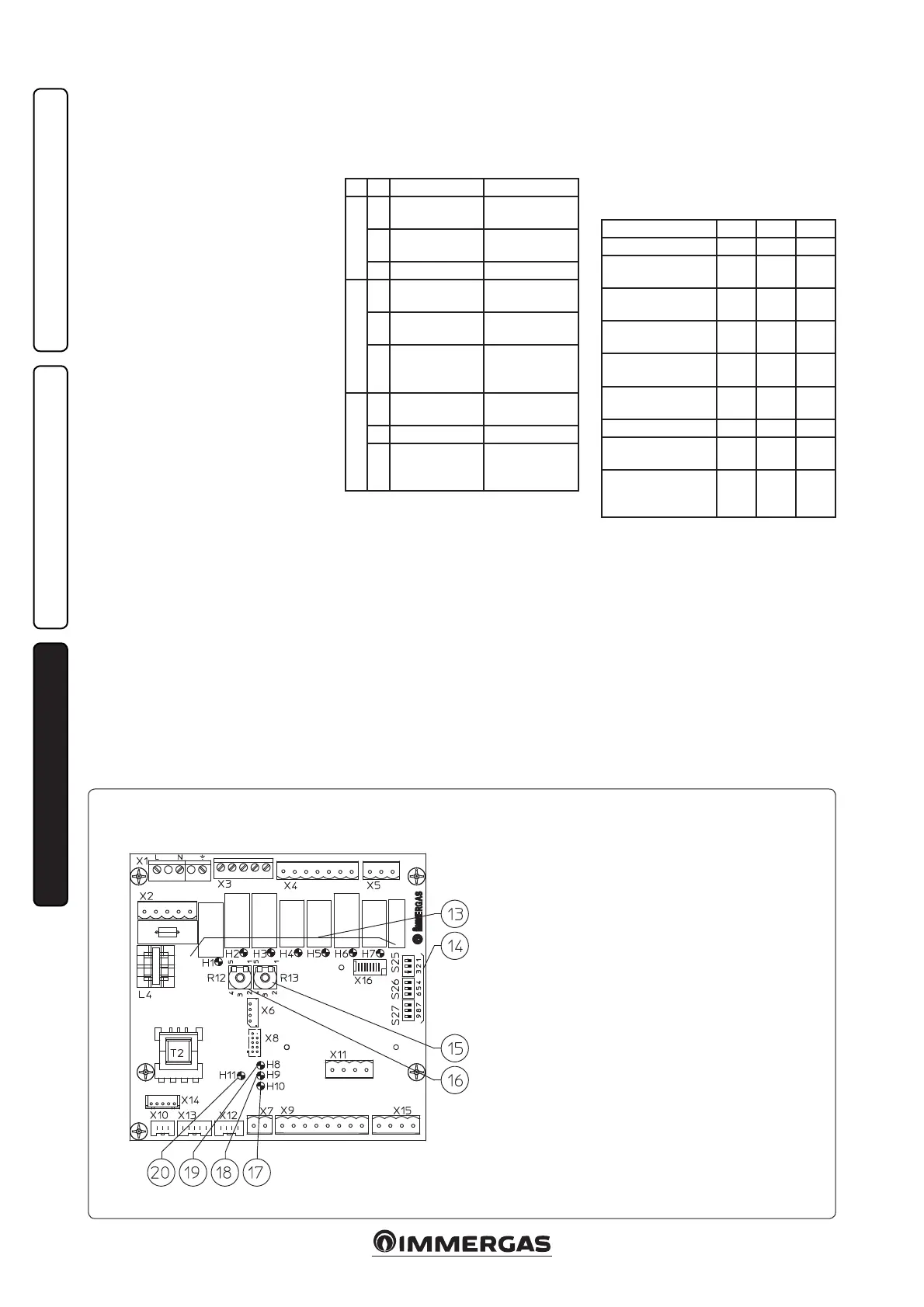
Zone management P.C.B.
Key:
13 - Relay functioning signal LED (H1 ÷ H7)
14 - Zone management board functioning mode selectors
15 - Zone 3 low ow temperature regulation trimmer.
16 - Zone 2 low ow temperature regulation trimmer.
17 - Board functioning status signal LED
18 - Board functioning status signal LED
19 - Board functioning status signal LED
20 - Board power supply signal LED