29
3-19
45
31
58
3-20
INSTALLERUSER
MAINTENANCE TECHNICIAN
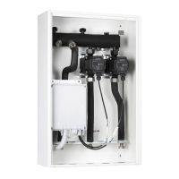
3.14 EXTERNAL TEMPERATURE PROBE
OPTIONAL.
e manifold is designed for the application of
the external probe (Fig. 3-19), which is available
as an optional kit. e probe can be connected
directly to the manifold P.C.B. or to the boiler
electrical system and allows the max. system
ow temperature to be automatically decreased
when the external temperature increases, in
order to adjust the heat supplied to the system
according to the change in external tempera-
ture. e external probe always operates when
connected, regardless of the presence or type of
room chrono-thermostat used, and can work in
combination with Immergas timer thermostats.
e external probe must be electrically connected
as indicated in the Fig. 3-5, 3-6, 3-11, 3-12, 3-13,
3-14 or 3-16.
• Control of the High-Temperature zone. e
correlation between ow temperature to the
system and external temperature is determined
by the parameters set on the boiler. See boiler
instructions manual.
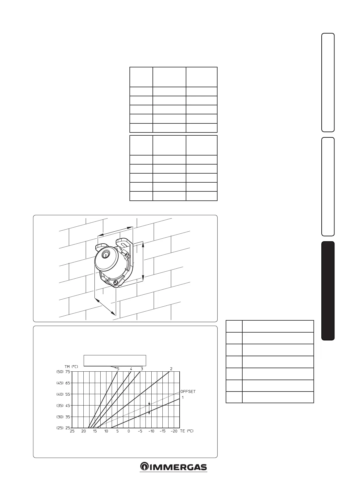
• Control of the Low-Temperature zone. e
correlation between ow temperature to the
system and external temperature is determined
by the position of the trimmer (15 or 16 Fig.
3-18) on the zone board according to the curve
represented in the diagram (Fig. 3-20).
• No external temperature probe. To set the ow
temperature of the low-temperature zones, it
is necessary to act using a screwdriver on the
trimmer (R12 or R13) present on the zone
control unit following the table provided below
(15 or 16 Fig. 3-18).
Low-temperature zone
Correction law of the ow temperature depending on the external temperature and user
adjustments of the central heating temperature.
FT = Low-temperature zone Flow Temperature
ET = External temperature.
Trimmer
position
R12 or R13
Low-temperature
zone ow
(25 ÷ 50 °C)
High-temperature
zone ow
(25 ÷ 75 °C)
1 25 °C 25 °C
2 30°C 37.5 °C
3 35°C 50 °C
4 40°C 62.5 °C
5 50 °C 75°C
Trimmer
position
R12 or R13
Low-temperature
zone ow
(35 ÷ 50 °C)
High-temperature
zone ow
(35 ÷ 75 °C)
1 35°C 35°C
2 39 °C 45°C
3 43 °C 55 °C
4 47 °C 65°C
5 50 °C 75°C
Note: using an IMG BUS connection to the
Superior kW boiler, the low-temperature zones
are regulated on the boiler display.
Note: when the external probe is connected, the
OFFSET action can be regulated (with Superior
kW boilers only).
3.15 TROUBLESHOOTING.
- Presence of air in the system. Check the open-
ing of the boiler vents, the central heating
system and the DIM, act on the 3-way mixing
valve, keeping it open for de-aeration (only for
H-LT and H-2LT version). Make sure the sys-
tem pressure and expansion vessel factory-set
pressure values are within the set limits; the
factory-set value for the expansion vessel must
be 1.0 bar, and system pressure between 1 and
1.2 bar.
- Low-temperature safety thermostat interven-
tion. It can depend on the blocked pump, the
blocked mixing valve or an anomaly on the
P.C.B. Check the correct operation of the com-
ponents indicated above, making sure that the
anomalies signalled by ashing of the LEDS H9
or H10 (according to the cases) on the P.C.B.
disappear.
- Low-temperature ow regulation NTC probe
anomaly. Replace the component and/or check
its correct operation, making sure that the
anomaly signalled via switch-on of the LEDS
H9 or H10 (according to the cases) on the
P.C.B. disappears.
- Low-temperature zone flow temperature
insucient or too low. It can depend on an
incorrect regulation of the trimmer (R12 or
R13) present on the P.C.B. from the blocked
or broken mixing valve (only for H-LT and
H-2LT version), or on the temperature set on
the lower boiler with respect to that requested
in the low-temperature circuit (only for boil-
ers connected without IMG BUS). Check the
correct regulation of the trimmer, check the
correct operation of the mixing valve (only for
H-LT and H-2LT versions). Make the boiler
function with a ow temperature over that set
for the low-temperature zone (only for boilers
connected without IMG BUS).
- e table below identies the errors displayed
on the boiler, when the manifolds are connect-
ed with the IMG BUS:
Code Description
32
Zone 2 Low-Temperature probe
anomaly
33
Zone 3 Low-Temperature probe
anomaly
34
Low-temperature zone 2 safety ther-
mostat intervention
35
Low-temperature zone 3 safety ther-
mostat intervention
36 IMG BUS communication loss
46
DIM safety thermostat intervention
(optional)
POSITION OF THE TRIMMER
ZONE P.C.B.
In brackets, temperature value with 25°/50° range