23
3-10
INSTALLERUSER
MAINTENANCE TECHNICIAN
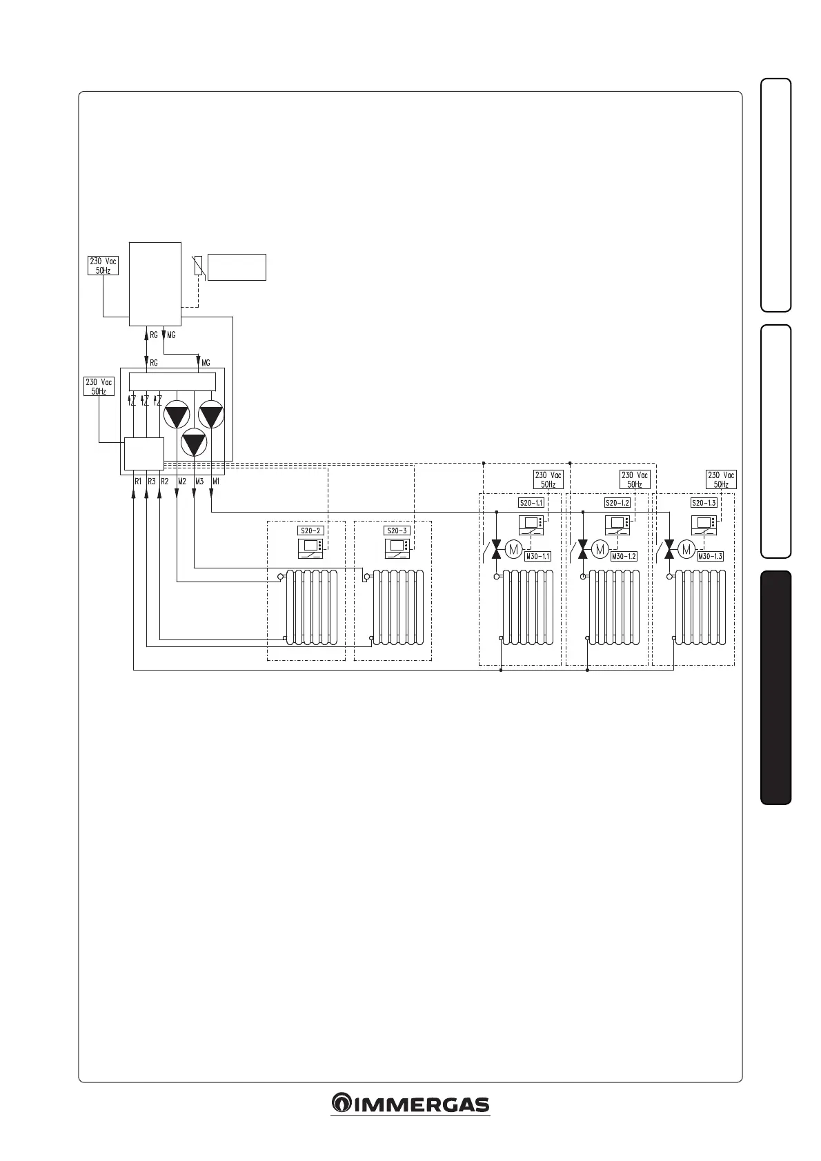
Example of hydraulic diagram for dividing zone 1 DIM into three portions.
Key
M30-1.1 - Portion valve 1 of zone 1
M30-1.2 - Portion valve 2 of zone 1
M30-1.3 - Portion valve 3 of zone 1
S20-2 - Room thermostat zone 2
S20-3 - Room thermostat zone 3
S20-1.1 - Portion 1 room thermostat of zone 1
S20-1.2 - Portion 2 room thermostat of zone 1
S20-1.3 - Portion 3 room thermostat of zone 1
BOILER
1st DIM V2 3 ZONES
Zone 2 Zone 3
Portion 1 of
zone 1
Portion 2 of
zone 1
Portion 3 of
zone 1
External probe
(optional)
Zones
control unit
DIM V2