26
3-15
INSTALLERUSER
MAINTENANCE TECHNICIAN
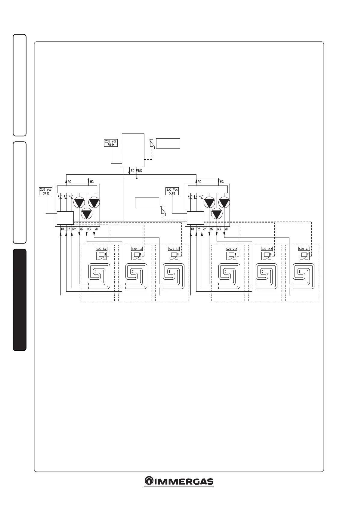
Example of hydraulic diagram for parallel connection of 2 DIM.
Key:
S20-1.1 - Zone 1 room thermostat 1st DIM
S20-1.2 - Zone 2 room thermostat 1st DIM
S20-1.3 - Zone 3 room thermostat 1st DIM
S20-2.1 - Zone 1 room thermostat 2nd DIM
S20-2.2 - Zone 2 room thermostat 2nd DIM
S20-2.3 - Zone 3 room thermostat 2nd DIM
1st DIM V2 3 ZONES
2nd DIM V2 3 ZONES
External probe
(optional)
External probe
(optional)
Zones
control unit
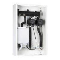
DIM V2
Zone 2 1st DIM Zone 2 2nd DIMZone 31st DIM Zone 3 2nd DIMZone 1 1st DIM Zone 1 2nd DIM
Zones
control unit
DIM V2
BOILER