9
1-5 1-6
INSTALLERUSER
MAINTENANCE TECHNICIAN
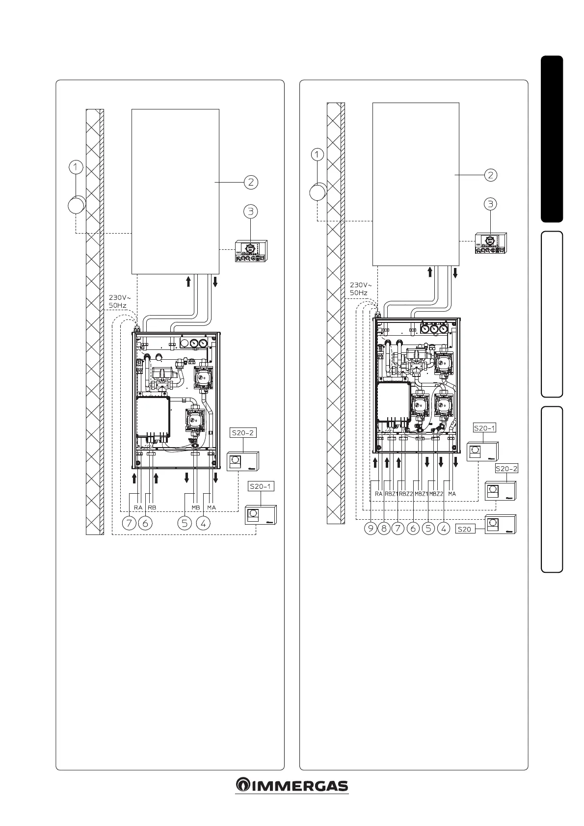
DIM A-BT installation layout (1 zone in H. T. and 1 zone in L. T.).
Key:
S20-1 - Zone 1 room thermostat (high temperature)
S20-2 - Zone 2 room thermostat (low temperature)
1 - External probe (optional)
2 - Boiler
3 - Comando Amico Remoto
V2
remote control (optional)
4 - High-temperature system ow
5 - Low-temperature system ow
6 - Return from Low-Temperature system
7 - High-temperature system return
Factory settings dene zone 2 as the main zone.
(See g. 3-3 for electrical connection and zone board setting)
DIM H-2LT installation layout (1 zone in H. T. and 2 zone in L. T.).
Key:
S20 - High-temperature zone room thermostat
S20-1 - Low-temperature zone 1 room thermostat
S20-2 - Low-temperature zone 2 room thermostat
1 - External probe (optional)
2 - Boiler
3 - Comando Amico Remoto
V2
remote control (optional)
4 - High-temperature system ow
5 - Zone 2 Low-Temperature system ow
6 - Zone 1 Low-Temperature system ow
7 - Zone 2 Low-Temperature system return
8 - Zone 1 Low-Temperature system return
9 - High-temperature system return
Factory settings dene zone 2 as the main zone.
(See g. 3-4 for electrical connection and zone board setting)