13
STEMkW Special ed 01/08 EOLO Mini kW Special
Technical Documentation
Technical Documentation
e circuit consists of an atmospheric burner and a modu-
lating gas valve for gas combustion and ow rate regulation
respectively.
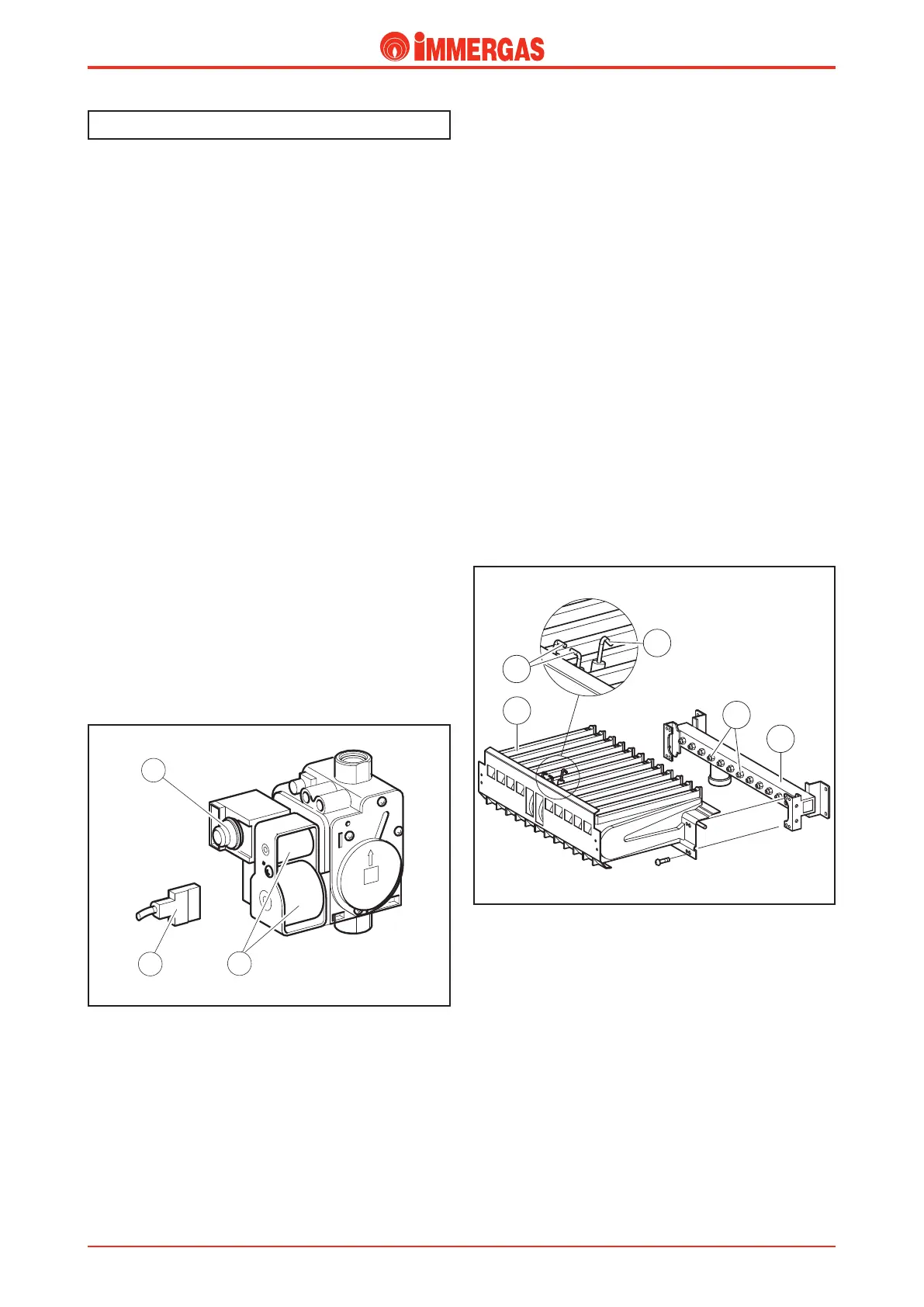
Operation.
When the main coils (3) are energised both the inner valve
shutters open allowing gas to ow through to the burner.
e ow rate/outlet pressure is regulated by means of the gas
valve stabiliser via the modulation coil (1).
By means of the burner (7) nozzles the fuel is injected into
the horizontal Venturi tubes (ramps) inside which an optimum
air-gas mixture is obtained that is ignited by the spark of the
ignition electrode (5).
Modulating gas valve.
e gas valve (SIT 845) features two main coils (3) and a
modulation coil (1) controlled by the integrated P.C.B..
e maximum and minimum outlet pressures can be set on
this valve (see gas settings).
Main electric coils (3).
ey are two ON-OFF type coils powered (230 V AC) by the
integrated P.C.B. when the burner has to be ignited.
ey are electrically connected in parallel and supplied by
mains voltage through a connector (2).
Modulating coil (1).
is is a low voltage coil controlled by the integrated P.C.B..
It controls the gas valve stabiliser and allows the outlet pres-
sure to be varied in a way proportionate to the DC current
running through it.
Gas circuit.
Burner.
e burner consists of horizontal Venturi pipes (6) inside which
the gas is injected by the same number of nozzles (7) mounted
on the manifold (8).
e number of nozzles, whose diameter varies according to
the type of gas utilised (see technical data) are 12 (24 version)
and 14 (28 version).
Ignition occurs thanks to a p.c.b. that controls both the ignition
(5) and detection (4) electrodes.
Ignition electrodes (5).
ey are controlled by the integrated P.C.B. that produces an
electrical charge between their ends, igniting the air-gas mixture
when they come into contact.
ey are located at the front of the burner, by the centre
ramp.
Detection electrode (4).
It is controlled by the integrated P.C.B. and detects burner
ignition.
It is located on the front of the burner on the same ramp as
the right ignition electrode.