24
STEMkW Special ed 01/08 EOLO Mini kW Special
Technical DocumentationTechnical Documentation
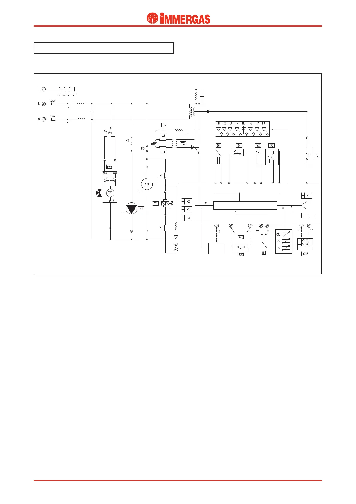
Electrical circuit.
Domestic hot water phase.
Operation.
Operation in the d.h.w. mode is enabled when the main switch
(R10) is on “SUMMER” or “WINTER”.
When domestic hot water is drawn it causes the contact of the
d.h.w. ow switch (S4) to close. Subsequently, if the tempera-
ture measured by the NTC ow probe (B1) is below that set
on the control panel (or on the Remote Control if installed), the
integrated P.C.B. powers the boiler circulator (M1) by means
of the K2 relay and, with the switching over of the K4 relay
contact, the motor (M) of the 3-way valve (M30) is powered
which keeps working until limit switch “1” opens when the
d.h.w. position is reached.
In the meanwhile, if the contact of the ue pressure switch
(S6) is idle “NC”, the adjustment circuit powers the fan (M20)
by means of relay K3.
With the enable of the safety thermostat (E4) and consequent
switching over of the ue pressure switch to “NO” (S6), the
P.C.B. sees to closing the contact of the request relay K1 that
causes the 2 contacts to close allowing the ignition cycle to
start, rst of all controlling the ignition electrodes (E1) and
then both the gas valve coils (Y1).
Burner ignition is detected by the integrated P.C.B. by means
of the ionisation electrode (E2).
HIGH
VOLTAGE
LOW
VOLTAGE
MICROPROCESSOR
ZONES
CONTROL
UNIT
NO
NC
Domestic hot water
Central heating