25
STEMkW Special ed 01/08 EOLO Mini kW Special
Technical Documentation
Technical Documentation
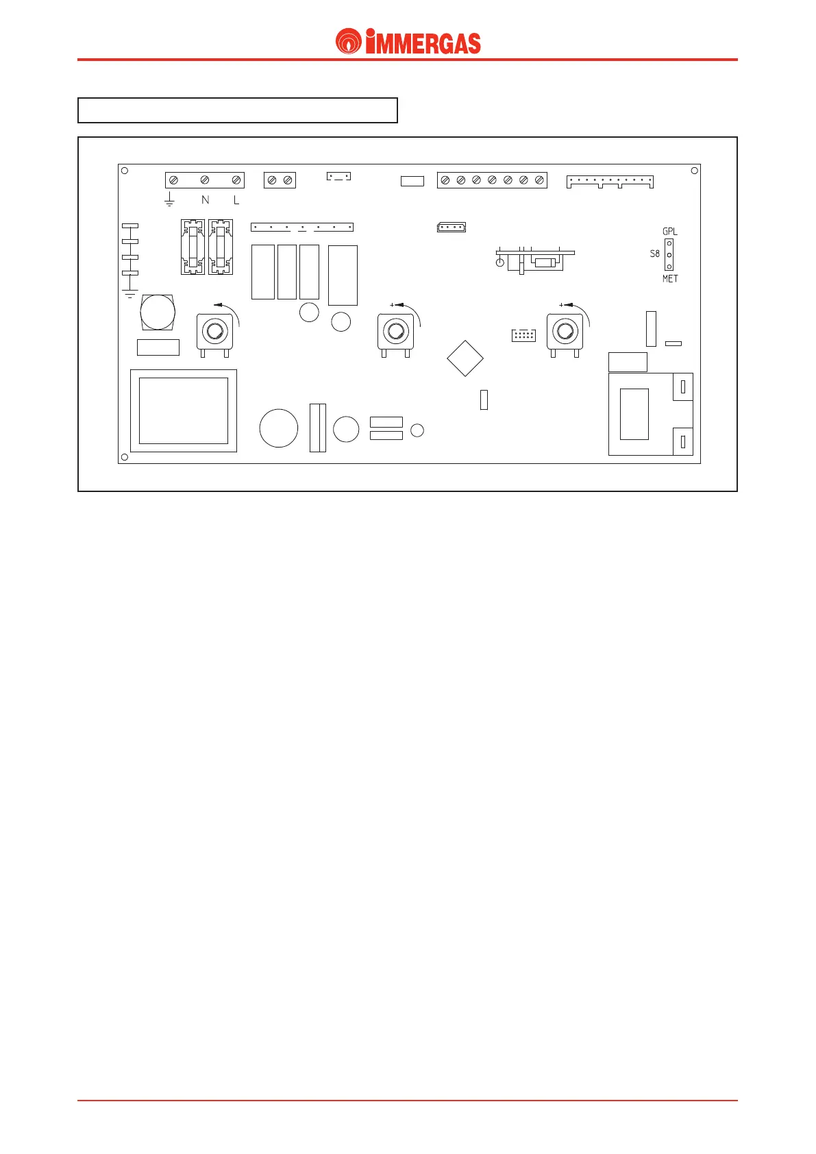
Modulation P.C.B..
Inside the boiler control panel an integrated electronic micro-
processor P.C.B. is located which manages electronic de vices
onP.C.B. of the appliance, it linearly modulates burner power
and thanks to a series of LED’s, shows the status of the applian-
ce, signaling when any safety device was activated.
e same P.C.B. is assembled on every model whether with
conventional ue or sealed chamber (EOLO/NIKE Mini kW
Special); rec ognition of the various types of boiler function is
automatic as it depends on how the boiler is wired.
A single printed circuit P.C.B. is supplied as spare part,
which via the relevant software and the setting of some
parameters, can be installed on EOLO/NIKE Mini kW
Special and AVIO/ZEUS kW boiler models (See printed
circuit board programming procedure).
Integrated P.C.B. is always powered regardless of main switch
(R10) position.
P.C.B. periodically self-tests in order to verify correct operation.
While operating in central heating mode or while the boiler is
in Stand-by, self-test function is enabled every 18 hours after
last test or last time the boiler was powered. In DHW mode,
self-test starts within 10 minutes after last time water was drawn
from the tap (self-test lasts approximately 10 seconds).
Warning: during self-test, the boiler and all signals remain
inactive.
Operation.
Central heating request.
By selecting the “WINTER” function with the main switch
(R10), the boiler is enabled to work in the central heating
mode.
When the contact of the room thermostat closes (S20), the
integrated P.C.B. powers the boiler circulator (M1) by means of
the K2 relay and, by the switching over of the K4 relay contact,
powers the motor (M) of the 3-way valve (M30) which keeps
working until limit switch “1” opens when the central heating
position is reached.
In the meanwhile, if the contact of the ue pressure switch
(S6) is idle “NC”, the adjustment circuit powers the fan (M20)
by means of relay K3.
With the enable of the safety thermostat (E4) and consequent
switching over of the ue pressure switch to “NO” (S6), and
if the temperature measured by the ow probe (B1) is under
that set on the control panel with the central heating tempe-
rature trimmer, the integrated P.C.B. excites the request relay
K1 that causes the 2 contacts to close allowing the ignition
cycle to start.
During the rst few seconds after the gas valve (Y1) has been
powered, the current to the modulating coil (Y2) is limited to
the predened soft ignition current. e burner will then go
to the minimum value set by setting the “Minimum Central
Heating Power*” parameter and then reach the maximum
value set (if required) by setting the “Maximum Central Hea-
ting Power*” parameter in a time set in the “Central Heating
Ramp Time*” parameter.
Subsequently the signal is varied directly proportionate to
the dierence between the temperature set with the central
heating temperature trimmer (R6) and that measured with
the ow probe (B1).
When the set temperature (+5°C) is exceeded, the contact of
the K1 relay opens and the burner switches o. Re-ignition
time depends on how the “Central Heating Ignitions Timer*”
parameter is set.
Each time the burner switches o the fan keeps working for
30 seconds.
'64&4
53"/4'03.&3
."*/4&-&$503
48*5$)
%0.&45*$)05
8"5&3
$&/53"-
)&"5*/(