IE
24
3
Solar circuit lling.
N.B.: If errors occur during installation, opera-
tion and maintenance, due to non compliance
with the technical laws in force, standards or in-
structions contained in this manual (or however
supplied by the manufacturer), the manufacturer
accepts no contractual and extra-contractual
liability for any damages and the appliance war-
ranty is invalidated.
e system can only be lled when:
- any operational residues have been eliminated
that may cause obstructions and deteriorate
the features of the glycol over time;
- any presence of water in the system has been
eliminated, which could otherwise cause dam-
age to the system in winter;
- the absence of leaks has been verified by
checks using air;
- the storage tank unit has been lled;
- the expansion vessel is preloaded as per the
manufacturer's or qualified professional's
instructions.
e system must be lled only using the glycol
supplied by Immergas via an automatic pump.
e system must be lled with vent valve closed.
Proceed as follows to ll the system:
1 connect the ow pipe of the automatic pump
to the tting of the lling valve (9 Fig. 4)
located under the pump and open the valve.
2 connect the return pipe of the automatic pump
to the tting of the draining valve (8 Fig. 4)
and open the draining valve.
3 The flow-rate regulator screw (11 Fig. 4)
must be orientated horizontally to ensure the
closure of the integrated ball valve. Leave the
thermometer in the reading position (ON).
4 ll the lling pump tank with the amount of
glycol necessary plus a minimum amount to
be le on the bottom of the tank in order to
prevent air circulating inside the circuit.
5 e lling stage must have a minimum dura-
tion of 20 ÷ 25 minutes. is time is required
to completely remove all air from the circuit.
Every now and again open the ow rate regula-
tor adjustment screw in order to eliminate air
from inside (vertical position).
6 Eliminate any air in the solar circuit preferably
using the so-called "pressure shot" method,
which consists in raising the lling pressure
of the circuit followed by a quick opening of
the return valve (8 Fig. 4). is method allows
air to be expelled from the circuit.
7 Close the lling cock and switch the lling
pump o, open the regulator screw of the ow
rate regulator (notch in vertical position).
8 Leave the circuit pressurised. Any pressure
drop indicates a leak in the system.
9 Set the functioning pressure in the circuit at
2 bar + 0.1 bar for every metre in the distance
between the solar collector and the expan-
sion vessel (practically, set the same pressure
between expansion vessel and system).
10 Switch the solar pump on at a maximum speed
and make it run for at least 15 minutes.
11 Disconnect the lling pump and close the
ttings using the relevant screw caps.
Do not ll the system in conditions with strong
insolation and with the manifolds at high
temperatures.
Make sure that all air bubbles have been com-
pletely eliminated.
Solar circuit vent.
Any air present in the system must be bled:
- on start-up (aer lling);
- if necessary, e.g. in the case of breakdown.
Attention: danger of burns from the liquid
contained in the collectors.
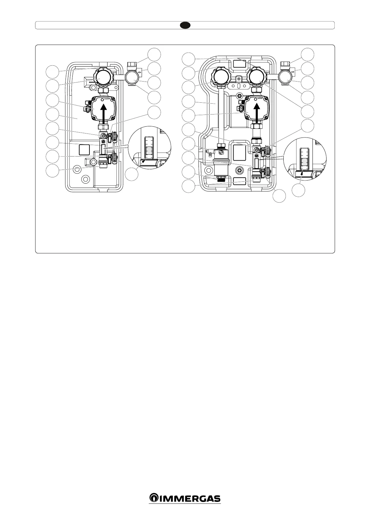
Main components.
Key:
1 - Solar pump
2 - Non-return valve, thermometer and
cock
3 - Valve drain tting
4 - Flow meter
5 - 6 bar safety valve
6 - 3/4” connection for expansion vessel
7 - Manometer
8 - Draining valve
9 - Filling valve
10 - Insulating casing
11 - Flow rate regulator
12 - Boiler inlet
13 - Output towards solar collector
14 - Reference for ow rate reading
15 - Non-return valve, thermometer and
cock
16 - Degasser
17 - Inlet from solar collector
18 - Output towards boiler
1
2
3
4
5
6
7
6
10
11
1
4
8
12
2
13
3
14
9
1
2
3
4
5
6
7
6
3
14
13
17
15
10
1
16
18
2
11
12
4
9
8
 Loading...