IE
25
Circulation pump.
e units are supplied with circulating pumps
tted with speed regulator.
ese settings are suitable for most systems.
In fact, the pump is equipped with electronic
control to set advanced functions. For proper op-
eration one must select the most suitable type of
operation for the system and select a speed in the
available range, with a focus on energy savings.
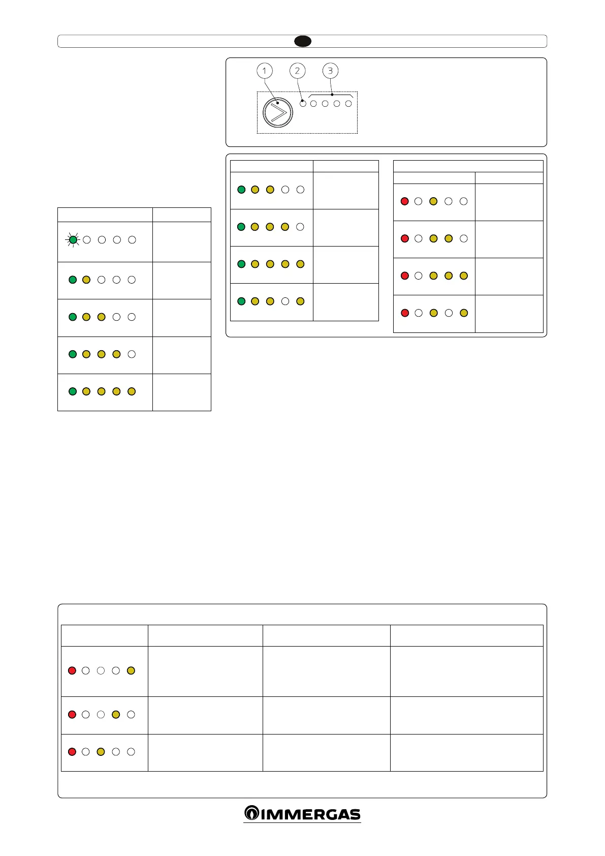
Display of operation status. During normal
operation, the status LED (2 Fig. 4) is switched on
and green (ashing (FL) when it is in stand-by),
the four yellow LEDs (3 Fig. 4) indicate the pump
absorption according to the following table:
Circulating pump LED Absorption
G Y Y Y Y
FL O O O O
Circulator in
stand-by
G Y Y Y Y
On On O O O
0 ÷ 25 %
G Y Y Y Y
On On On O O
25 ÷ 50 %
G Y Y Y Y
On On On On O
50 ÷ 75 %
G Y Y Y Y
On On On On On
75 ÷ 100 %
Selection of operating mode. To see the cur-
rent operation mode simply press the button
once (1 Fig. 4).
To change operation mode press the button
for between 2 to 10 seconds until the current
conguration ashing, each time the button is
pressed all possible functions are scrolled cycli-
cally according to the table (Fig. 5). Aer a few
seconds without doing any operation the circula-
tor memorises the selected mode and goes back
to operation display.
- Constant curve: the pump operates with a con-
tant curve. e circulator working point will
move up or down according to the system's
demand.
- PWM Profile: do not use this operation
mode.
Selection button lock. e button has a feature
that locks its operation to prevent accidental
modications, to lock the control panel it is
necessary to press button (1) longer than 10
seconds (during which the current conguration
ashes), the active lock is signalled by all LEDs of
the control panel ashing. To unlock the button
press again longer than 10 seconds.
Real time diagnostics: in the event of malfunc-
tion the LEDs provide information on the circu-
lator operation status, see table (Fig. 6):
Circulating pump LED
(rst red LED)
Description Diagnostics Remedy
R Y Y Y Y
On O O O On
Circulator pump blocked
e circulator pump cannot restart
automatically due to an anomaly
Wait for the circulator to make automatic
release attempts or manually release the mo-
tor sha acting on the screw in the centre of
the head.
If the anomaly persists replace the circulator.
R Y Y Y Y
On O O On O
Abnormal situation (the circulator
continues operating).
low power supply voltage
Voltage o range Check power supply
R Y Y Y Y
On O On O O
Electrical fault
(Circulator pump blocked)
e circulator is locked due to power
supply too low or serious malfunction
Check the power supply, if the anomaly persists
replace the circulator
Key:
1 - Function selection button
2 - Green (G) / red (R) LED
3 - 4 yellow LEDs (Y)
4
6
5
Circulating pump LED
Description
G Y Y Y Y
On On On O O
Constant curve
speed 1
G Y Y Y Y
On On On On O
Constant curve
speed 2
G Y Y Y Y
On On On On On
Constant curve
speed 3
G Y Y Y Y
On On On O On
Constant curve
speed 4 (default)
DO NOT USE
Circulating pump LED
Description
R Y Y Y Y
On O On O O
PWM Prole
speed 1
R Y Y Y Y
On O On On O
PWM Prole
speed 2
R Y Y Y Y
On O On On On
PWM Prole
speed 3
R Y Y Y Y
On O On O On
PWM Prole
speed 4