6
45
31
58
1-4
1-7
1-8
1-5 1-6
INSTALLERUSER
MAINTENANCE TECHNICIAN
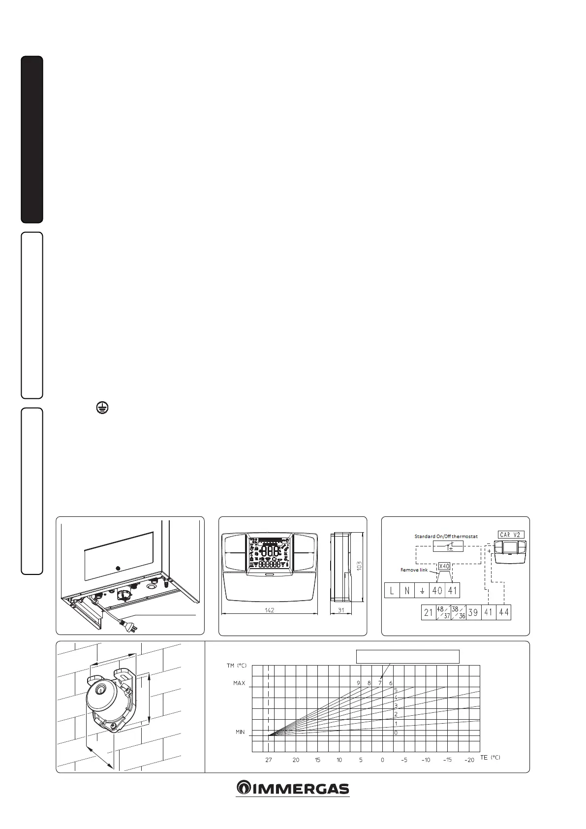
POWER SUPPLY CABLE
Condensate drain. To drain the condensate
produced by the appliance, it is necessary to
connect to the sewer system by means of acid
condensate resistant pipes i.e. p.v.c. having an
internal diameter of at least 13 mm. e system
connecting the appliance to the drainage system
must be carried out in such a way as to prevent
freezing of the liquid contained. Connections
must comply with national and local regulations
on discharging to waste waters, condensate must
not discharge to storm water. Pipes must be on
gradient to drain.
N.B.: ll the trap with water before operating
the boiler.
Electrical connection: The “INTEC 12-30
SYSTEM EXTERNAL” boiler has an IPX5D
protection rating for the entire appliance.
Electrical safety of the appliance is reached only
when it is correctly connected to an ecient
earthing system as specied by current safety
standards.
Attention: Immergas/Hunt Heating declines
any responsibility for damage or physical injury
caused by failure to connect the boiler to an
ecient earth system or failure to comply with
the reference standards.
Also ensure that the electrical installation
corresponds to maximum absorbed power
specifications as shown on the boiler data-
plate. The boilers come complete with a 1.5
metre power cable that includes an Australian
electrowelded plug. The plug is of type I,
compliant with standard AS 3112. e power
cable must be connected to a 240V ±10% / 50Hz
mains respecting L-N polarity and the earth
connection
. When replacing the power
supply cable, contact a qualied technician (e.g.
Hunt Heating Service Dept) (Fig. 1-4).
In the event of mains fuses replacement on the
connection board, use 3.15A fast fuses. For the
main power supply to the appliance, never use
adapters, multiple sockets or extension leads.
Note: If the condensate cannot be on a gradient
and terminate to drain, then a suitable condensate
neutraliser must be used (available for purchase
from Hunt Heating).
1.5
REMOTE CONTROL CAR
V2
OPTIONAL.
e boiler is prepared for the application remote
control CAR
V2
, which is available as optional kit.
(Fig. 1-5).
Immergas remote control CAR
V2
is connected
with 2 wires only. Carefully read the user and
assembly instructions contained in the acces-
sory kit.
• In addition to the functions described in the
previous point, the CAR panel
V2
enables the
user to control all the important information
regarding operation of the appliance and the
heating system with the opportunity of easily
intervening on the previously set parameters
without having to go to the place where
the appliance is installed. e CAR
V2
panel
is equipped with self-diagnosis to display
any boiler functioning abnormalities. The
climate chrono-thermostat incorporated into
the remote panel enables the system flow
temperature to be adjusted to the actual needs
of the room being heated, in order to obtain
the desired room temperature with extreme
precision and therefore with evident saving in
running costs. e chrono-thermostat is fed
directly by the boiler by means of the same 2
wires used for the transmission of data between
boiler and chrono-thermostat.
CAR
V2
(Optional). e operations described
below must be performed aer having removed
the voltage from the appliance. Any CAR
V2
must
be connected by means of terminals IN+ and
IN- (on the CAR
V2
terminal plate), respecting
polarity at boiler PCB, where IN+ connects to
terminal 44 and IN- connects to terminal 41
(See Fig. 1-6).
Attention: if the Comando Amico Remoto
V2
(CAR
V2
) remote control is used, arrange two
separate lines in compliance with current
regulations regarding electrical systems. No
boiler pipes must ever be used to earth the
electric system or telephone lines.
Ensure elimination of this risk before making
the boiler electrical connections (ALL
ELECTRICAL CONNECTION MUST MEET
ALL LOCAL REGULATIONS).
1.6 EXTERNAL PROBE OPTIONAL.
e boiler is prepared for the application of the
external probe (Fig. 1-7), which is available as an
optional kit. Refer to the relative instruction sheet
for positioning of the external probe.
The probe can be connected directly to the
boiler electrical system and allows the max.
system ow temperature to be automatically
decreased when the external temperature
increases, in order to adjust the heat supplied to
the system according to the change in external
temperature. e external probe always operates
when connected, regardless of the presence or
type of room chrono-thermostat used and can
work in combination with Immergas chrono-
thermostats. e correlation between system
flow temperature and external temperature
is determined by the position of the selector
switch on the boiler control panel according to
the curves shown in the diagram (Fig. 1-8). e
electric connection of the external probe must be
made on clamps 38 and 39 on the boiler P.C.B.
(Fig. 3-2).
NB: Thermostat connections if using own
after market thermostat, after removing
manufacturers link, connect to terminals 40
and 41 (Fig. 3-2).
Position of the central heating temperature
user adjustment