8
C
12
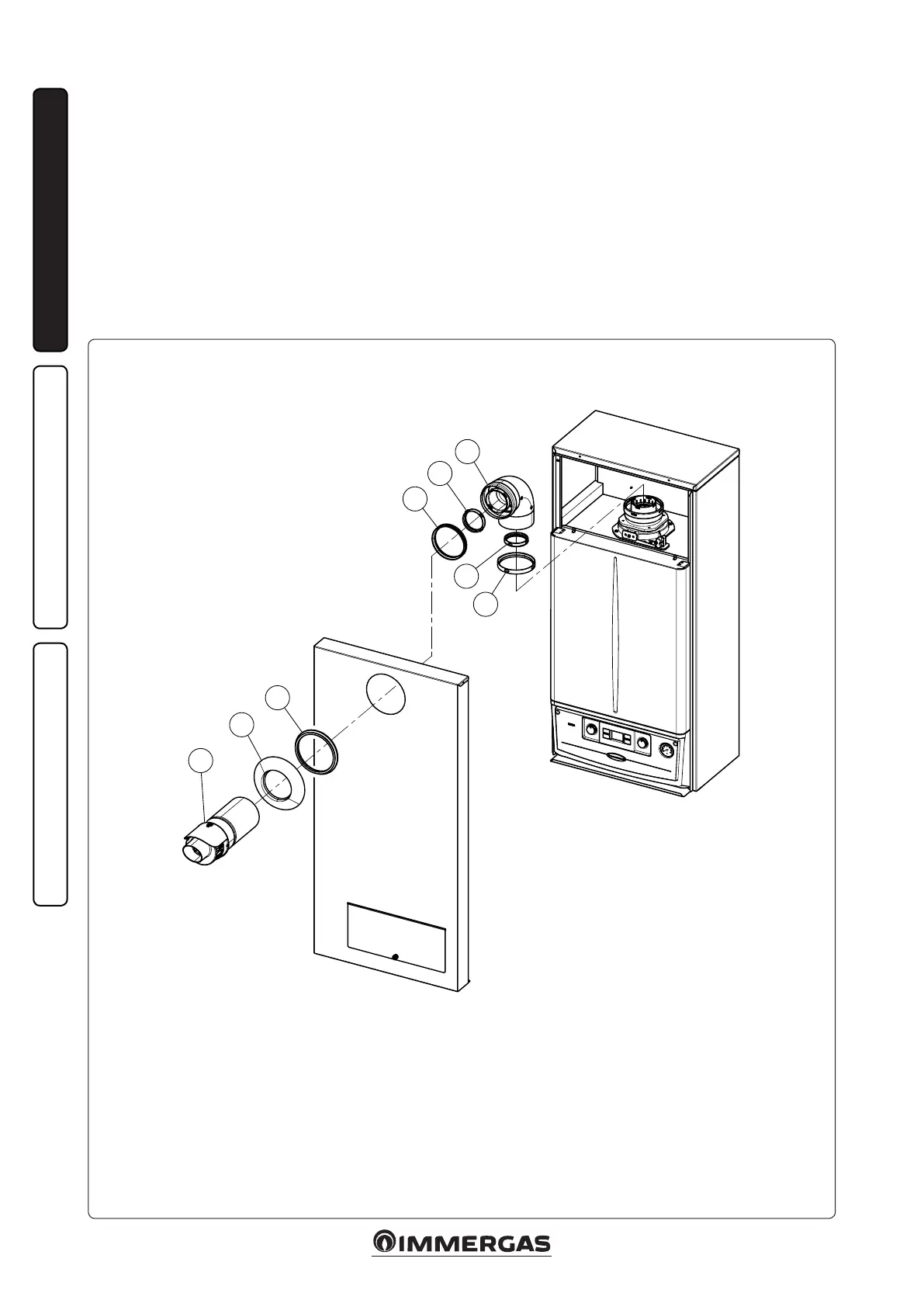
1-9
2
1
3
4
5
6
7
8
INSTALLERUSER
MAINTENANCE TECHNICIAN
1.8 INSTALLATION OF INTAKE /
EXHAUST TERMINALS.
• Type C conguration, sealed chamber and
fan assisted.
Horizontal intake - exhaust terminal Ø60/100
(supplied as standard). Assembly (Fig. 1-9):
install the gaskets (1) and (2) in the concentric
ange (already installed).
Couple the bend (3) with the concentric ange up
to the stop aer having checked that the gaskets
are tted (4) and (5) in the female end.
Mount the casing front referring to Paragr. 3.14.
Couple the terminal pipe (8) with the male end
(smooth) into the female end (with lip seals) of
the bend (3) up to the stop, making sure that
the external wall sealing plate (7) has been tted
and checking it is on the casing front and gasket
(6); this will ensure proper sealing and joining
of the elements.
Components:
Concentric ange intake gasket (1)
Concentric ange exhaust gasket (2)
90° concentric bend (3)
90° concentric bend exhaust gasket (4)
90° concentric bend intake gasket (5)
Gasket (6)
External wall sealing plate (7)
Concentric intake/exhaust terminal Ø 60/100 (8)
Flue kit complete 60/100 Australia code: 3.026007
N.B.: Flue conguration supplied standard
with all INTEC external boilers.