16
STMiN3E ed 09/11 MINI NIKE 3 E
Technical DocumentationTechnical Documentation
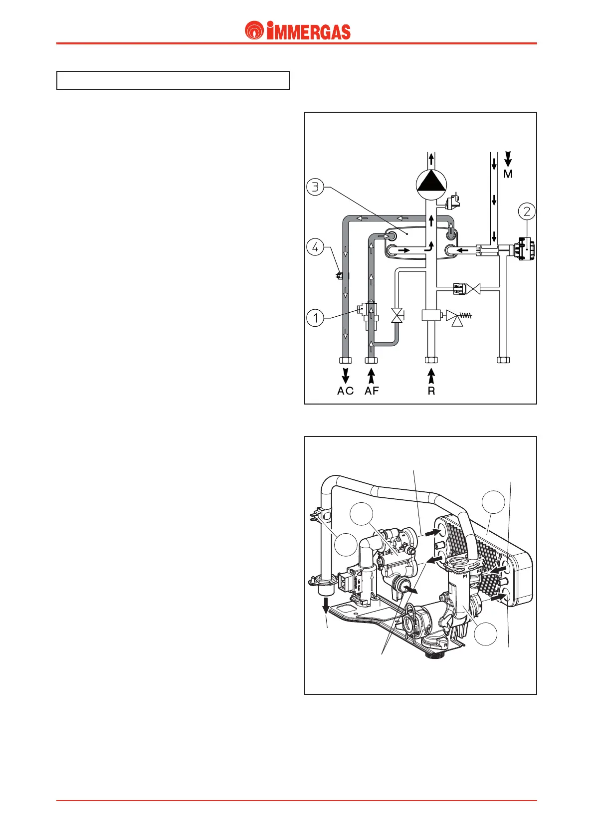
How it operates
Use of the DHW leads to cold water passing through the ow
switch (1) and the consequent closure of the electric contact
that is coupled to it (see electric circuit).
After this, the integrated P.C.B. starts up the phase for DHW
priority that causes the burner to turn on, and if a CH request
is in underway, it also starts up the deviation of the 3 way valve
(2) which subsequently moves to the work position (see how
the 3 way hydraulic valve operates).
is causes the ow pipe (M) to close and simultaneously open
the passage towards the DHW heat exchanger (3).
In this way circulation inside the CH system is prevented,
while it is allowed in the plate heat exchanger, inside which
domestic cold water absorbs the heat contained in the primary
circuit water (see DHW heat exchanger).
e CH phase is excluded in this phase and priority is given
to the production of DHW.
e water/water heat exchange occurs inside the domestic
water heat exchanger (3) which is screwed onto the body of
the domestic water inlet (1) and the body of the domestic
water outlet (2).
e upper left part of the body allows domestic cold water to
enter, while the lower part allows the return of the primary
circuit.
In the same way the upper part right part of the body allows
DHW to ow out and the lower part allows the primary
circuit to ow.
Secondary circuit (Domestic Hot Water Circuit)
1
3
2
4
Domestic cold
water inlet
Flow
primary circuit
Return
primary circuit
Water outlet
DHW
Domestic hot
water outlet
Flow
primary circuit
Return
primary circuit