18
STMiN3E ed 09/11 MINI NIKE 3 E
Technical DocumentationTechnical Documentation
e circuit is composed of an atmospheric burner and a
modulating gas valve, which respectively allow the combustion
of the gas and the adjustment of its ow rate.
How it operates
e electric power supply of the main coils (3) causes the
opening of both internal shutters of the valve, thus allowing
the passage of gas towards the burner. e outlet ow/rate
pressure is then adjusted by acting on the gas valve stabiliser
by means of the modulation coil (1).
e fuel is injected , by means of the burner nozzles (6), into
the horizontal Venturi pipes (ramps). Here, an optimal air-gas
mixture is obtained that is ignited by the spark of the ignition
electrode (4).
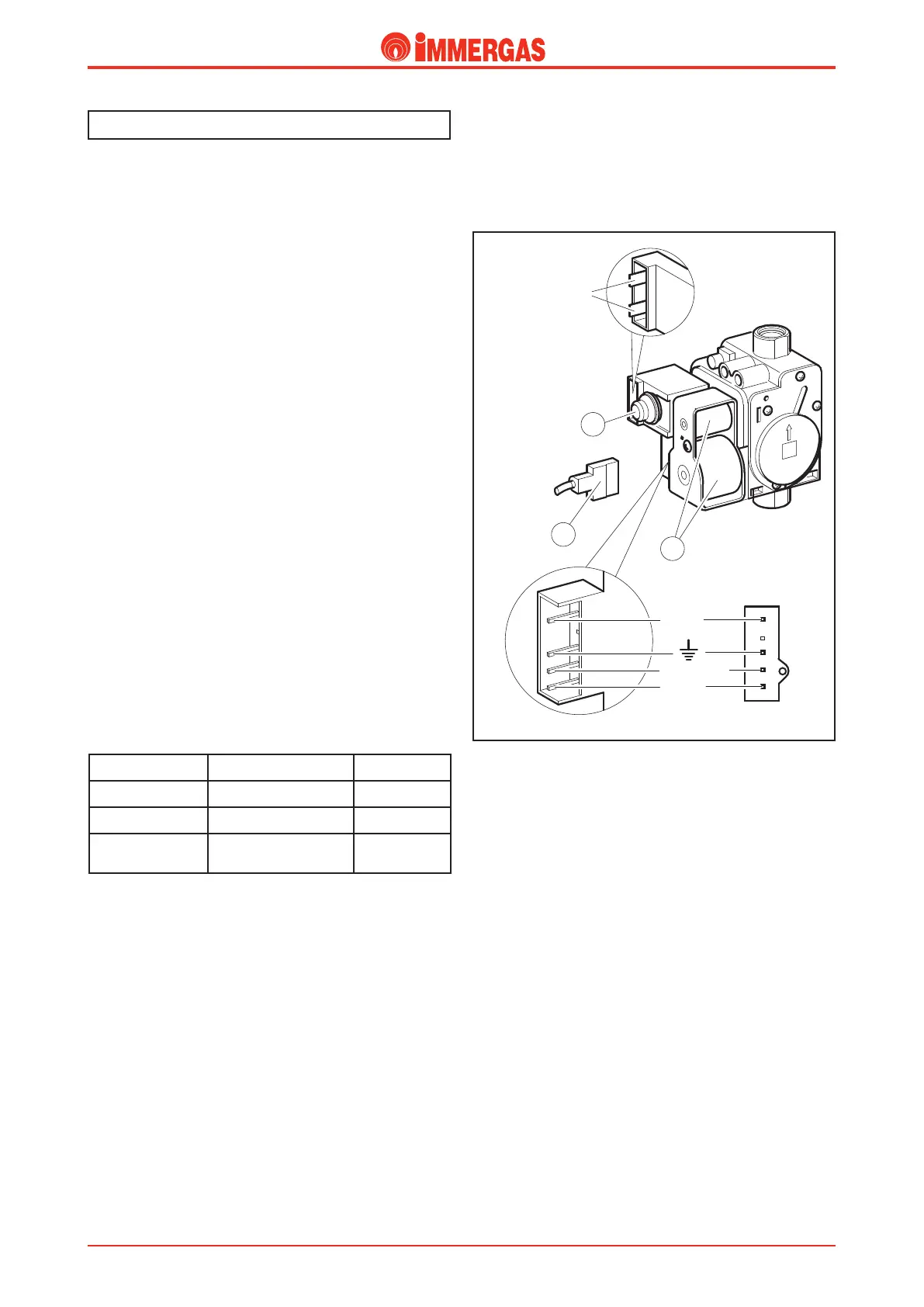
Modulating gas valve (SIT 845)
e gas valve is equipped with two main coils (3) and a
modulation coil (1) controlled by the integrated P.C.B.
The maximum and minimum outlet pressure values are
calibrated on the valve (see gas adjustments).
Main electric coils (3)
ey are two ON-OFF coils that are powered (230 V AC) by
the integrated P.C.B. when burner ignition is necessary.
ey are connected electrically in parallel and powered by the
mains voltage through a specic connector (2).
Modulation coil (1)
It is a low voltage coil that is controlled by the integrated P.C.B.
It acts on the gas valve stabiliser and allows the variation of
the outlet pressure proportionally to the direct current that
passes through it.
Gas circuit
COIL POWER SUPPLY RESISTANCE
EV1 230 V AC 6.25 kΩ
EV2 230 V AC 860 Ω
Modulation coil
250mA DC (G20)
320mA DC (L.P.G.)
22 Ω
Standard values for the boiler at maximum capacity
1
3
2
Modulation
coil
Connector
viewed from the
gas valve
EV1
EV2
Common