18
STVP ed 02/06 VICTRIX Plus
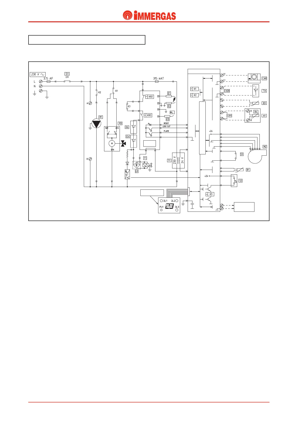
Electrical circuit.
Heating phase.
Operating with a room thermostat.
With the main switch (S1) on WINTER it powers the modu-
lating control board and enables operation in the heating
mode.
When the room thermostat contact (TA) closes, the low volt-
age circuit starts the pump (M1) by means of the K2 relay
contact.
e flow of water intercepts the pump pressure switch (S2)
whose contact, on closing, energises the coil of relay K3.
At the same time, the adjustment circuit causes the relay K1
contact to divert until the 3-way diverter valve (M3) motor (M)
is powered. is motor keeps working until the limit switch
“A” opens when the central heating position is reached.
If the temperature measured by the NTC heating sensor (B1)
is below that set on the control panel with the heating poten-
tiometer, the low voltage circuit starts the fan (M2) and then
closes the contact of the request relay (K3).
Hence the control unit (IGN. BOARD) starts the ignition
cycle, first energising the ignition electrodes (E1-E2) and then
with the possible tripping of the fume thermostat (E6) both
gas valve coils (Y1) after it has been enabled by the overtem-
perature thermostat (E4).
Burner ignition is detected by this same control unit (IGN.
BOARD) by way of the ionisation electrode (E3).
Operation with the Amico Remote Control.
With the main switch (S1) on SUMMER, the modulating
control board and the Amico Remote Control (CAR) are
powered.
If the conditions detected by the Amico Remote Control
(CAR) require ignition in the heating phase (CAR SUM/WIN
selector switch on WINTER, heating temperature setting above
that detected by the heating sensor (B1), room temperature setting
higher than that read), the board turns the pump (M1) on by
means of relay K2 and ignition occurs as described above.
Note: In both cases, each time the control unit switches off due to
the set temperature having been reached, the modulating control
board turns the burner off in the heating phase for 180 seconds.
Technical DocumentationTechnical Documentation