19
STVP ed 02/06 VICTRIX Plus
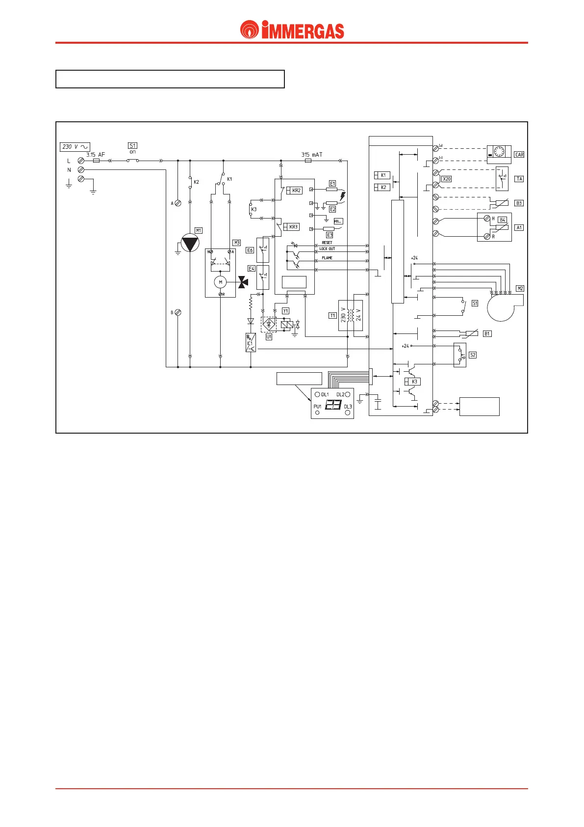
Electrical circuit.
Domestic Hot Water Phase
.
Operation
.
With the main switch (S1) on SUMMER or WINTER, the
modulating control board is powered and operation in the
domestic hot water mode is enabled.
If the temperature detected by the NTC d.h.w. sensor (B4) is
below that set on the control panel (or on the CAR if installed)
the adjustment circuit starts the pump (M1) by means of the
relay K2 contact.
e flow of water intercepts the pump pressure switch (S2)
whose contact, on closing, energises the coil of relay K3.
At the same time, the adjustment circuit causes the relay K1
contact to divert until the 3-way diverter valve (M3) motor
(M) is powered. e motor keeps working until limit switch
“N” opens when the central heating position is reached.
e low voltage circuit starts the fan (M2) and then closes the
contact of the request relay K3.
Hence the control unit (IGN. BOARD) starts the ignition
cycle, first energising the ignition electrodes (E1-E2) and then
with the possible tripping of the fume thermostat (E6) both
gas valve coils (Y1) after it has been enabled by the overtem-
perature thermostat (E4).
Burner ignition is detected by this same control unit (IGN.
BOARD) by means of the ionisation electrode (E3).
Technical Documentation
Technical Documentation