20
STVP ed 02/06 VICTRIX Plus
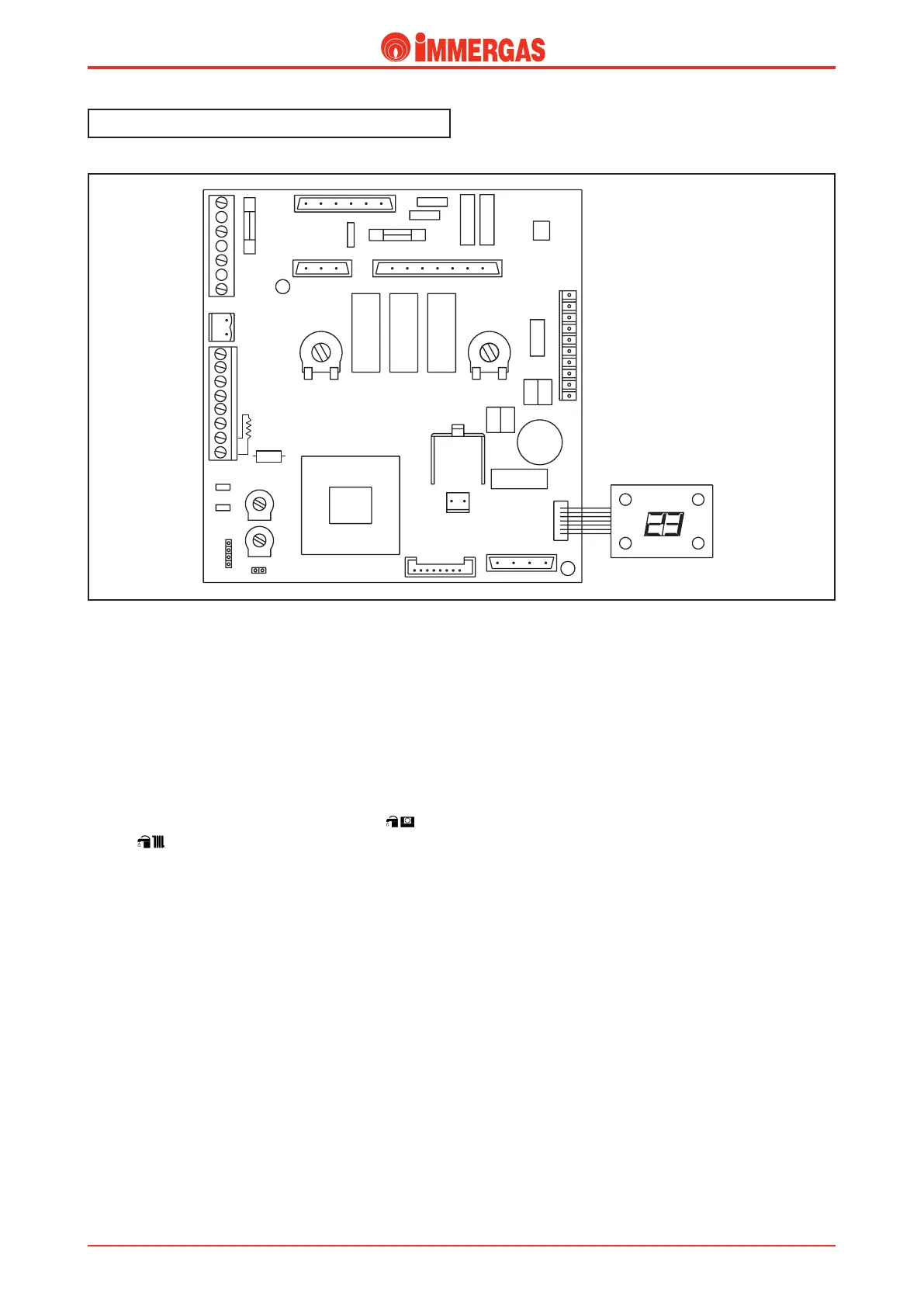
Modulating Control Board.
e boiler features a microprocessor-controlled electronic
board used both on models with the electric 3-way diverter
valve (VICTRIX Plus, VICTRIX Zeus) and on models with the
hydraulic 3-way diverter valve (VICTRIX).
To have the appropriate operating type, act on jumper R6
(jumper present = electric 3-way diverter valve, jumper
absent = hydraulic 3-way diverter valve).
e board is connected to a socket (DISPLAY BOARD)
which, by means of LEDs and a display, shows the boiler
operating status.
e board is powered by the main switch (S1) on (sum-
mer) or (winter).
Operation.
Heating request with a room thermostat.
With the main switch (S1) on WINTER and the room
thermostat contact (TA) closed, the low voltage circuit starts
the circulator (M1) by means of relay K2 and powering the
3-way diverter valve (M3) motor (M) by means of the relay
K1 contact.
e flow of water intercepts the pump pressure switch (S2)
whose contact, on closing, energises the coil of relay K3.
If the temperature read by the heating NTC sensor (B1) is
lower than that set with the heating potentiometer (HEAT),
the fan (M2) starts.
On reaching a speed of 700 rpm (minimum speed for ignition
validation) the board closes the contact of the request relay
(K3).
is results in power reaching the control unit (IGN. BOARD)
and the start of the ignition cycle.
During the ignition phase, the fan works at a speed equal to
half the top speed set with the fan speed adjustment trimmer
(FAN POT.).
Once the flame has been detected (signal from the control unit),
speed is changed (modulated) in a way directly proportionate
to the difference between the temperature set with the heating
potentiometer (HEAT) and that read with the heating NTC
sensor (B1) and, if necessary, reaches the maximum set value
in 50 seconds (maximum heating output).
Once the set value is exceeded, the contact of relay K3 opens
and the burner switches off. To restart the burner you have to
wait at least 180 seconds.
Heating request with the Amico Remote Con-
trol.
If the conditions found by the Amico Remote Control (CAR)
require operation in the heating phase (SUM/WIN selector
switch on WINTER, time programmer request, room temperature
setting above that found), the low voltage circuit starts the circu-
lator (M1) by means of relay K2 and powers the 3-way diverter
valve (M3) motor (M) by way of the K1 relay contact.
e flow of water intercepts the pump pressure switch (S2)
whose contact, on closing, energises the coil of relay K3.
If the temperature read by the heating NTC sensor (B1) is
below that set with the Amico Remote Control (CAR) heating
potentiometer, the fan (M2) starts.
Once a speed of 700 rpm is reached (minimum speed for igni-
tion validation) the board closes the contact of the request
relay (K3).
R1
FAN
SPEED
POT
.
C.H.
POT
.
CM1
PUMP
SWITC
CM2
C.H.
TEMP.
SWITC
H
DL1 DL2
DL3
PU1
Technical DocumentationTechnical Documentation