10
• The electric supply must not be interrupted or zeroed for more than 3 ms at any time. Between two interruptions it
must not take more than 1 s.
• The interruptions must not overcome 20 % of the tension peak for more than one cycle. Between two interruptions it
must not take more than 1 s.
The manufacturer assumes no liability for any damages to people, things and animals caused by the non-compliance of
the above instructions
Chapter 5 IN FUNCTION - USE
DANGER
WARNING
Before setting the machine in motion it is essential that the Operator and Safety
Ma
nager have read the Instructions Manual and understood all parts of the
machine and activities linked to it (Risks, Dangers, Functionality, Operation,
Protections, Commands, etc.)
5.01
MACHINE CALIBRATION – METERS - INDICATORS
The machine is checked in the factory, using sample equipment periodically checked by officially recognised institutes.
These checks cannot guarantee that the machine, meters and indicators will provide accurate values and results
conforming to the standards in force in the countries the machine has been installed and used in.
Normally such norms envisage calibration check after every movement. In order to obtain correct values and results it
is therefore VITAL that the operator, once the machine has been installed and set up and before official tests, has an
officially recognised body check the machine characteristics, its calibration and results/values reliability. The
manufacturer is exempt from all responsibility in the case of direct and indirect damage from use of the machine without
officially approval by the relevant bodies.
5.02 PLACEMENT ( ONLY SV007 & SV008 MODELS)
For these sieves is important the placement
The vibrant maximum power can reach values such as to
require fixing to the floor of the magnetic shaker.
If the shaker is used more frequently at low intensity values of
vibrant, it is not necessary to fix the shaker to the floor, but if the
shaker is used at its most vibrant intensity should be fixed to the
floor.
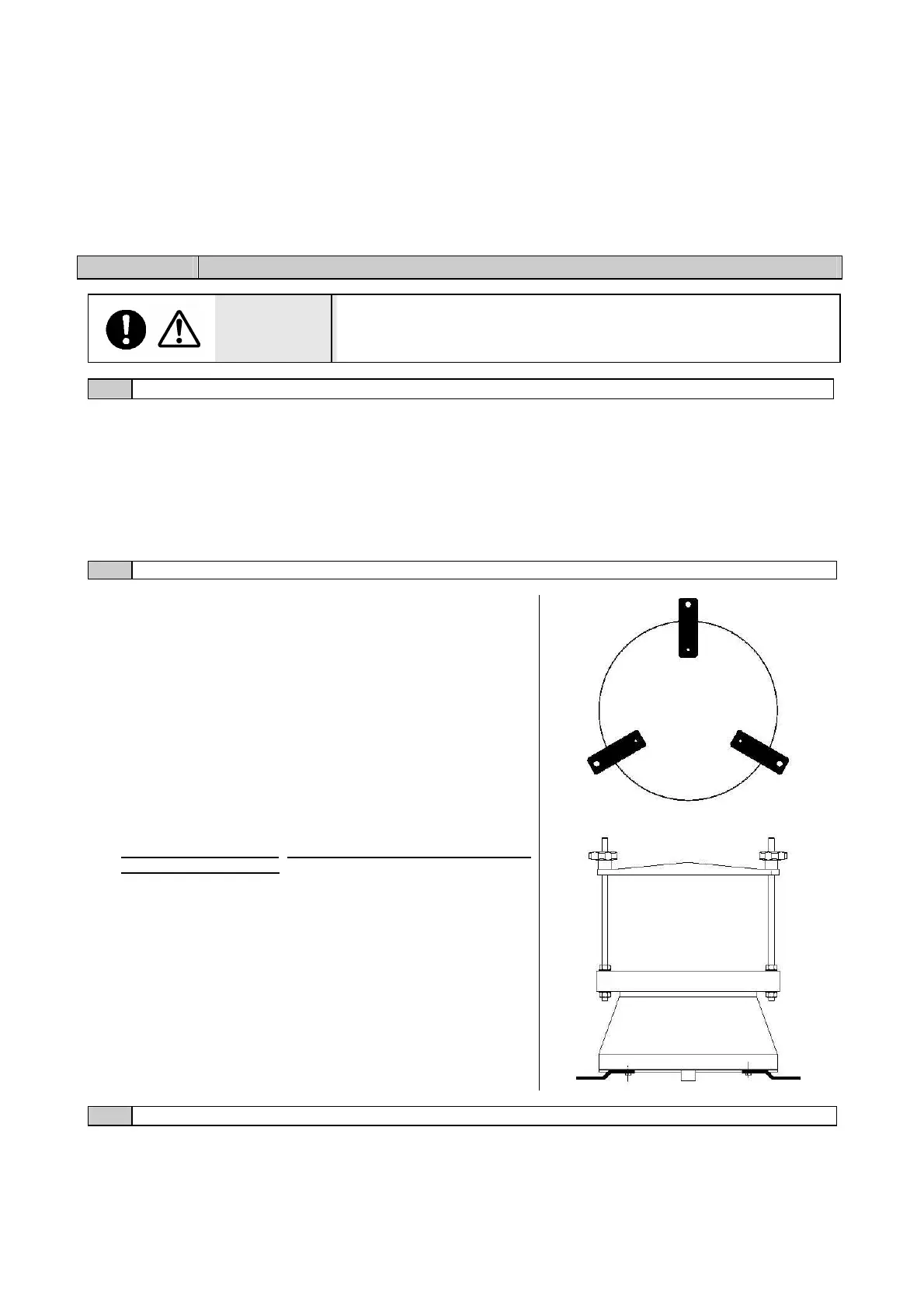
The shaker has 3 brackets with holes for fixing to floor, to fix
the shaker, follow these instructions:
Unscrew the three screws and three washers on the
bottom of the shaker.
Interpose the 3 brackets between the bottom of
setaccitatore and the screw heads (see diagram
opposite),and tighten screws.
Use the outer holes
of the brackets to anchor the
shaker to the ground.
N.B.: To anchor the brackets to the floor you must check
carefully the floor:
A. If the floor is very compact and resistant (concrete or
similar) is sufficient use of expansion bolts with a
penetration depth of 70mm
B. If the floor has a consistency less than concrete or if is
composed by friable materials you must use fixing bolts
In these cases it is necessary to use fixing bolts
anchored to the floor by foundations cemented to the
floor.
5.03
EQUIPPING
We give here the right procedures in order which allow to an inexperienced operator tooling up the sieve
shaker properly:
INSTALLATION OF THE THREADED RODS