6
Chapter 2 TECHNICAL CHARACTERISTICS
2.01
GENERAL MACHINE DESCRIPTION
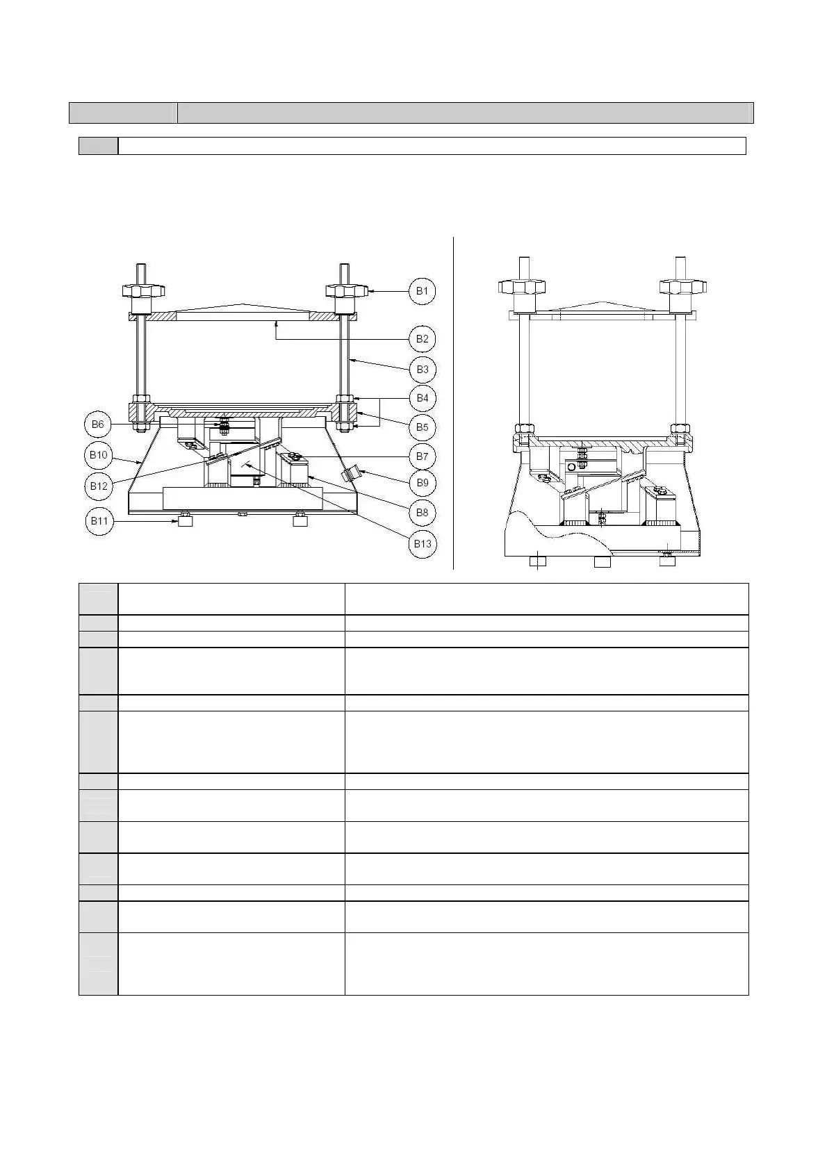
The equipment is basically formed by a plate holder for specimens (B5). This is supported by springs (B12)
and is activated by electromagnetic impulses (B13). The sieves are subjected to a double vibrating action:
vertical and rotational.
A059-01 KIT
B1
BLOCKING KNOBS
They secure the upper bar (B2) to the sieves, blocking them
firmly to the receiver (B5).
B2
BAR It secures the sieves to the specimen receiver (B5).
B3
THREADED BARS They allow to regulate the bar height (B2).
B4
FIXING NUTS
They fix the threaded bars (B3) to the specimen receiver. In the
shaker A059-01 KIT is present only one pair of data and the bars
B2 are screwed into the sieve holder B5
B5
SIEVE HOLDER It can hold several sieves according to the operator’s needs.
B6
ADJUSTMENT SCREWS
They allow to fix and to adjust the specimen receiver (B5) to the
electromagnet (B13). In this way, the vibrations produced by the
electromagnet are transferred to the sieves placed on the
receiver (B5).
B7
FIXING SCREWS These screws fix the springs (B12) to the support columns (B8).
B8
SUPPORT COLUMN FOR SPRINGS
It allows connecting the base to the specimen receiver (B5) by
means of the springs (B12).
B9
CABLE FIXING DEVICE
It fixes the feeling cable to the sieve shaker base, avoiding its
incidental pull during the normal working procedures.
B10
GUARD
It allows reaching the inside components of the sieve shaker
base. The guard is fixed to the base by some screws.
B11
SUPPORTING FEET They allow laying the sieve shaker steadily on any surface.
B12
SPRINGS
They transfer the vibrations from the electromagnet (B13) to the
specimen receiver (B5).
B13
ELECTROMAGNET
It generates the vibrations, which are necessary for a sieving
test. Using the Control Panel (C) it is possible to modify the
vibrating intensity according to the user’s needs. (See Chapter
“USE” of this manual for further details).