99903514:TELESCOPIC CRANE:
2-4 SECTION 2: MAINTENANCE
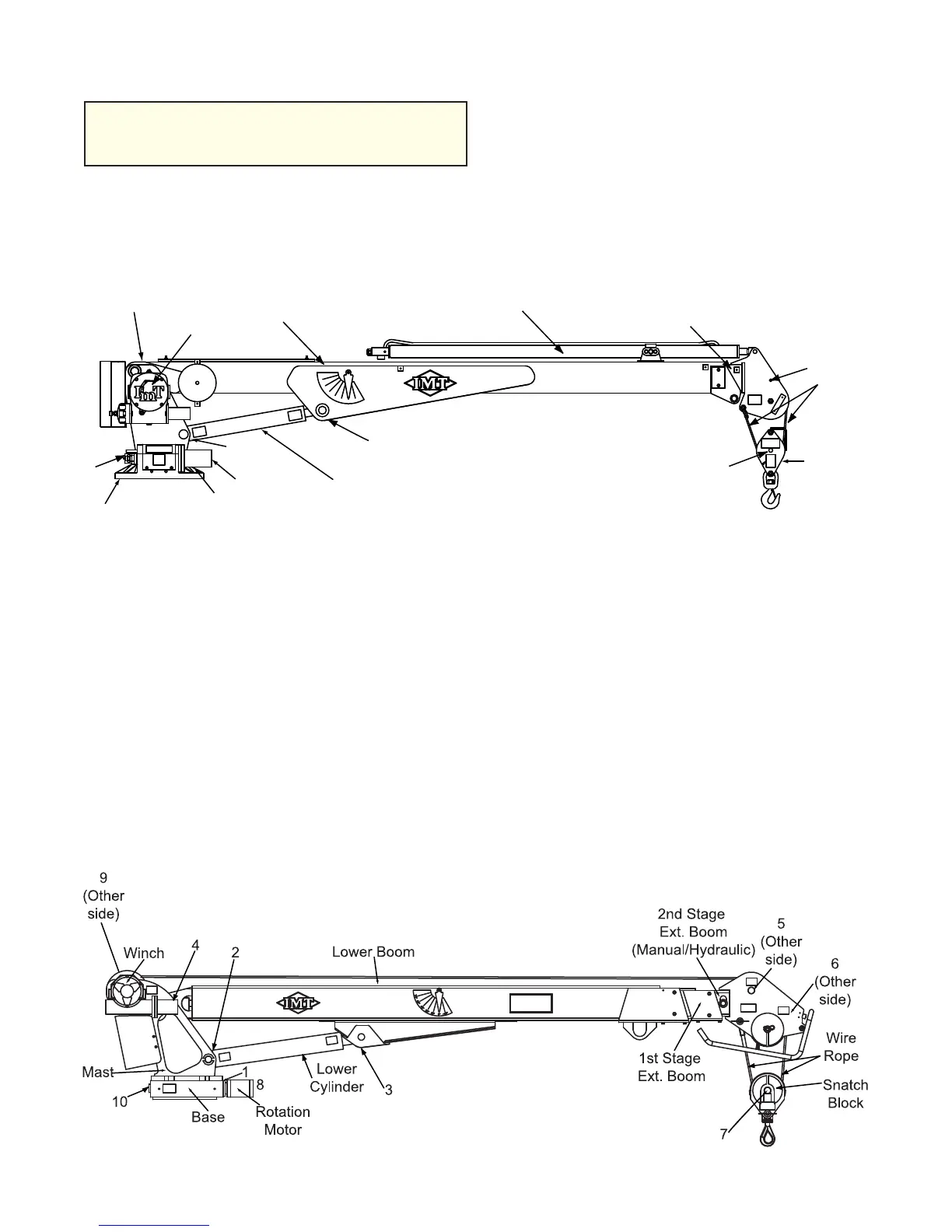
Figure B-5: Component & Grease Zerk
Locations - Models 3020, 3820 & 5020
1. Gear Rotator Grease Extension
(Rotate crane while greasing)
2. Lower Cylinder Base
3. Lower Cylinder Rod
4. Mast/Lower Boom Hinge Pin
5. Upper Sheave Pin
6. Lower Sheave Pin
7. Snatch Block Sheave Pin
8. Worm Drive Bearings (3 pumps, then
rotate fully) (Model 5020 only)
9. Winch Outboard Bearings
10. Worm Gear Bearing Zerks (2)
Figure B-4: Components & Grease
Zerk Locations - Models 1015 & 2020
1. Worm Gear
2. Turntable Bearing - Grease Extension
3. Lower Cylinder - Base End
4. Lower Cylinder - Rod End
5. Mast/Lower Boom Hinge Pin
6. Sheave Pin
7. Snatch Block
Lower Cylinder
1
2
3
4
30˚
60˚
45˚
75˚
15˚
0˚
-15˚
Rotation
Motor
Base
Mast, 5
Winch
Lower Boom
Extension Cylinder
1st Stage Ext. Boom
(Manual or Hydraulic)
Wire
Rope
Snatch
Block
6
7
MODELS 1015 & 2020
MODELS 3020, 3820, & 5020
NOTE
COMPONENTS ON CRANE DIAGRAMS ARE
IDENTIFIED BY NAME; GREASE ZERKS ARE
IDENTIFIED BY NUMBER.
20030115
 Loading...


