3
Site Requirements
Total Containment Volume*
Minimum - 0.25 gallons (1 L)
Maximum - 500 gallons (1879 L)
*Refer to manufacturers’ installation
guides or data sheets to calculate
containment area volumes.
**All containment areas MUST be
compatible with the vacuum levels
listed.
Normal Operating Vacuum 2" – 6" Hg (1 – 3 PSIG)
Pre-Programmed Maximum
Shutdown (Alarm Condition)
9" Hg (4.5 PSIG)
Mechanical Relief Valve
Vacuum**
10" Hg (5 PSIG)
Jumper Tubing Use only supplied vacuum tubing
Vacuum Sensor Wiring
Belden No. 87761(0.12" OD) to 400 ft.
Belden No. 89182(0.31" OD) to 500 ft. (maximum distance)
Solenoid Wiring
600 V, 18 AWG minimum, UL approved
refer to ANSI/NFPA70 or CEC electrical codes
Note: SCM should be tested annually after installation.
The term containment (in secondary containment) refers to the interstitial spaces of double walled piping, sumps and
tanks that serve as a secondary containment if the primary containment is damaged.
Individual containment sections of a given product pipeline may be jumpered together via a vacuum line to form one larger
single containment. An example of ‘jumpered’ containment spaces is the secondary containment layer of product piping
from the turbine containment to the rst dispenser, and then jumpered to the secondary containment layer of the same
product piping on the other side leading to the next dispenser containment area.
Several containment areas may be grouped together and used with a single Secondary Containment Control Module (TS-
SCCM). No more than four (4) SCM groups should be used per pump siphon. The combination of any containment group
may not exceed the volume limits listed for SCM.
Note: DO NOT jumper tank interstitials with other tank interstitials or other containments.
Note: DO NOT jumper containment areas of unlike product pipelines together.
Note: If grouping multiple containment areas together, the installer will need to purchase and use the vacuum hose,
ttings, and clamps to secure the connection as specied by FFS.
Note: Both intrinsically safe and explosion proof conduits need to be available inside of the turbine containment for the
TS-SCCM.
Available Congurations
Refer to Franklin Fueling
Systems’s current Fuel
Management Systems
Product Catalog for
a complete listing
of the current SCM
congurations offered.
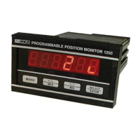
Note: The SCCM 1 (as
pictured in Figure
2) can monitor one
containment group
and the SCCM
2 can monitor
two containment
groups.
TS-SCCM/1 TS-SCCM/2 TS-SCCM Side View
Figure 2 – SCCM 1 and SCCM 2 Dimensions