27
• DOK-DIAX01-TDA********-PRJ1-EN-E1,44 • 07.97
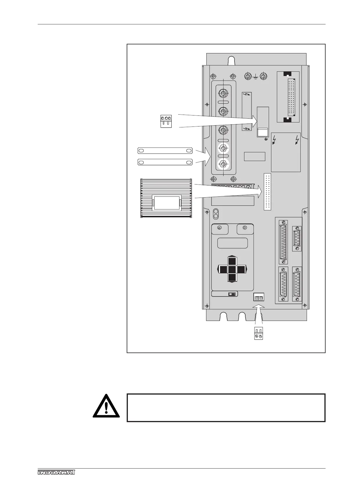
The electrical connection accessories comprise the following parts:
2. Control cabinet design
Fig. 17: Electrical connection accessories E••-TDA
The controllers of a drive package must be separately earthed
to the supply module! Minimum conductor cross-section of
the earthing cable is 10 mm
2
!
The connection diagram for the specific controller connections corre-
sponding to its location within the drive package is indicated in Fig. 15.
Typisierung:
Fertigungsnummer:
X1
ATTENTION!
BLOWER SUPPLY VOLTAGE
Lüfterspanngung
220VAC
X8
L+
L-
A3
A2
A1
DANGER HIGH VOLTAGE
AC - MAINSPINDEL DRIVE
READY FAULT
X11
Bb Bb
X3 X5
X2 X4
Parameter
MOTOR POWER OUTPUT
Motoranschluß
1 2 3
T1 T2
X12
SWITCH OFF
VOLTAGE BEFORE
CHANGING MODULE
AS
Prog. Modul AS
nicht unter
Spannung wechseln
DANGER POWER
300 VDC INPUT
DISCHARGE TIME
Entladezeit > 1 Min.
POWER SUPPLY OUTPUT
VOLTAGE RATING, MUST
NOT EXCEED POWER
INPUT VOLTAGE DATA
Nur mit Versorgungsein-
heit gleicher od. kleinerer
POWER-Spannungs-
angabe betreiben
ATTENION!
NEVER REMOVE OR INSTALL THIS
PLUGS WHILE VOLTAGE IS APPLIED
BLACK CABLE ON THE BOTTOM!
Verbindung nie unter Spannung
lösen bzw. stecken.
Schwarze Leitung immer unten!
Plug-in terminal for
motor thermistor
connection
Rails for DC link circuit bus
Control voltage bus
connecting cable
Plug-in terminal for
"Ready" contact
ZubanTDA.fh3
Busbars for DC link circuit
Control voltage bus conn.
cable
Elec. conn. access. parts
Min. cross-section, earthing
cable
Motor thermis conn.
plug-in terminal
Plug-in terminal for ready
contact
Plug-in terminal for motor
thermistor conn.
Ready contact, plug-in
terminal