16
• DOK-DIAX01-TDA********-PRJ1-EN-E1,44 • 07.97
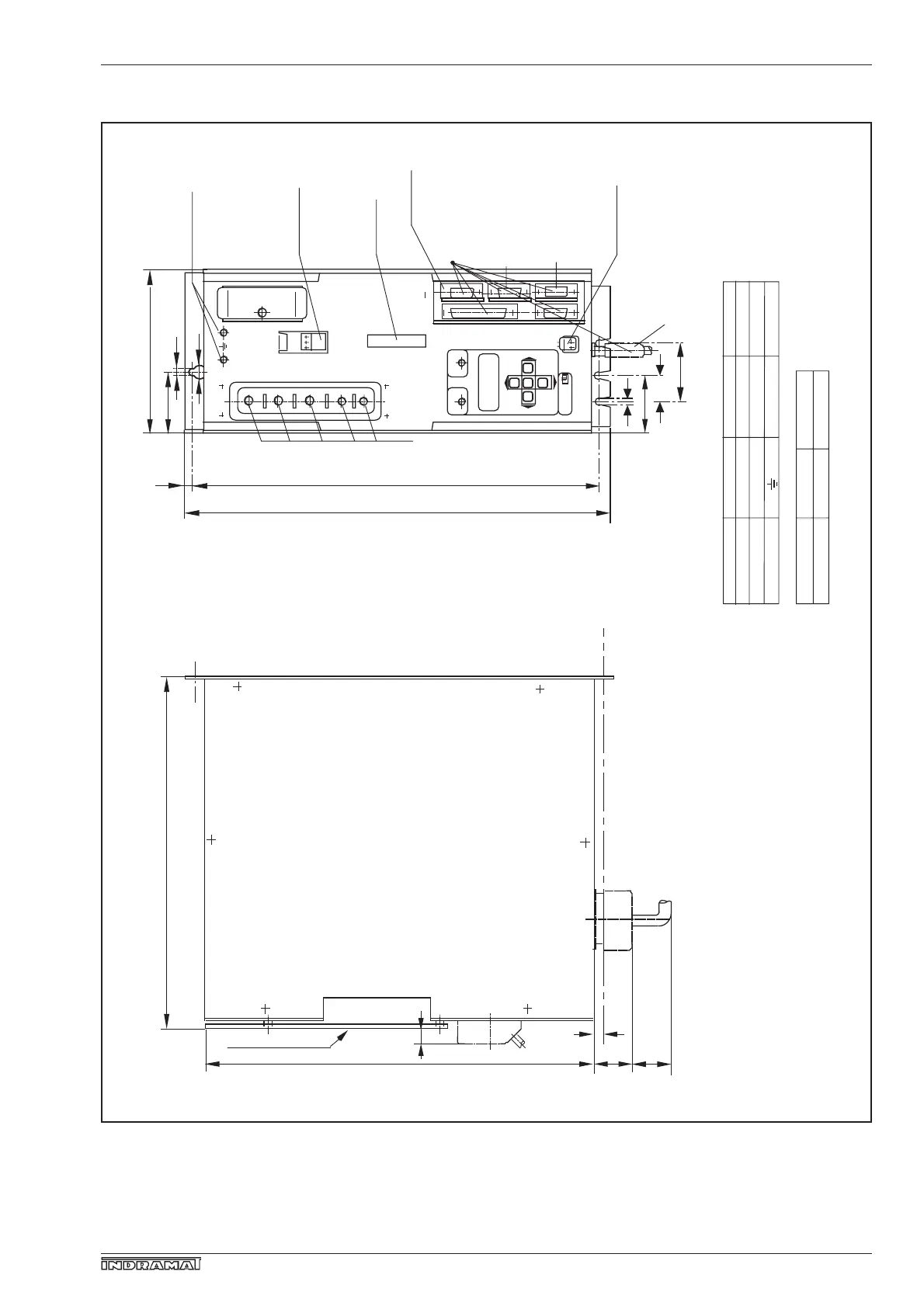
2.2. Mechanical data
2. Control cabinet design
Fig. 8: Dimensional specification of main spindle controller TDA 1
A1
A2
A3
L-
L+
X1
X8
READY
X3
X5 (option) additional
encoder input
X4
52.5
373
±0.2
390
X2
X11
X12
Programming
module AS 7
FAULT
LCD display
PARAM.-
Earthing bolt
325
355
10
Protection against contact
(transparent plate)
Stud bolt
Plug-in terminal
3-pin
Plug-in connector
16-pin
X6 (option)
additional interface
Tightening torque ratings of stud bolts
Motor connection
D.C. link circuit
Earthing
Terminal desig.
A1, A2, A3
L+, L-
Thread size
M6
M5
M5
Tightening torque
5Nm
3Nm
3Nm
Weights:
TDA 1.1-
in [kg]
50
10.5
100
10.5
Permissible orientation: vertical (earthing stud at the top!)
8
50
50
Maße_TDA
front view
D-sub plug-in
connector
X5a (option)
synch. input
7
52.5
30
60
13
7
8
150
X4 (option)
speed set-point
Plug-in terminal,
2-pin)
D-type subminiature connector Tightening torque for stud bolts
Dimensions Stud bolts
Earthing bolt Weight, TDA 1 controller
Inspection plate Plug-in terminal
Plug-in terminal strip Protective cover