IDS 410/422 User's Manual
59
ISOLATED ANALOG OUTPUT OPTION IDS410/422-AO
The Analog Output option board is internally mounted inside the IDS indicator. The Analog
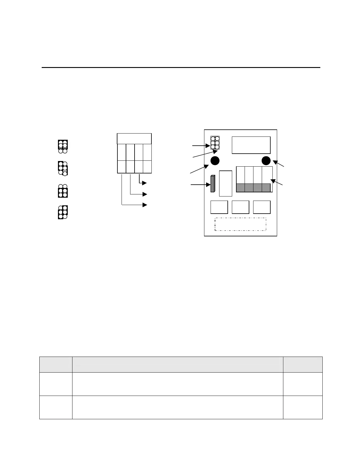
Output has two jumpers; JP1 & JP2. These jumpers are used to configure the output format.
Terminal block TB1 is for making external wiring connections. JP1 & JP2 are factory set for 4-
20mA. Refer to the diagram below for configuration, format and alternative wiring. No
interconect cabels are provided by the factory, the recomended cabels used should be suitable for
the conduit fittings and should comply with National Electrical code requirments.
INSTALLATION OF ANALOG OUTPUT BOARD
Before installation, remove power from the IDS indicator and remove the back plate to access the
internal board. Refer to the drawings below to locate the installation connector and stand off
holes on the IDS 410/422 weight indicators. Install the (2) plastic standoffs into the holes on the
CPU board and plug the analog output board (J1) onto the analog output connector. Secure the
analog output module to the CPU board by pushing the standoffs through the holes on the
module. Set JP1 and JP2 according to the desired output and connect the external device to TB1
according to the selected output. Apply power to the IDS indicator and configure parameters 81,
82, and 83 as described in the table below.
SETUP PARAMETERS
For proper operation, the following parameters are used to configure the operation of the analog
output.
Paramete
r
Description Default
Value
81 Analog output span (20ma). The value entered here is the display graduations
(weight/count-by) and must correspond with the full scale digits set in
parameter 17
10,000
82 Analog output offset (4ma). The value entered here is the display graduations
(weight/count-by) and must correspond with the full scale digits set in
parameter 17
0
10 VDC output
R4 option
1 2 3
Ground
Voltage
Current
0- 5 VDC output
4-20 ma output
0-24mA output
0-20mA output
U3
1 2 3 4
J1 16 pin header
JP1
JP2
TB1
U2
Stand
off
off
R4 option