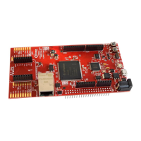
AURIX™ lite Kit V2
Hardware Description
Board Users Manual 12 Revision October, 2020
2.3.3 miniWiggler JDS
The miniWiggler JDS is a low cost debug interface which allows you access to the device via DAP. Make sure
that you have the latest DAS release. Debugging is possible via the DAS Server ‘UDAS‘. Please contact your
preferred debug vendor for support of DAS. If you have connected the board to the PC and there runs the DAS
server, then a working connection is visible via the green LED5 (ADBUS4). The status LED6 (ADBUS7/green) is
switched on/off through the DAS Server, depending on the used debugger (client).
IMPORTANT: Make sure that there is no or a tristated connection on the DAP connector if the LED5
(miniWiggler in use) is on.
2.4 Reset
The power on reset input pin (/PORST) of the AURIX™ family is a bi-directional input/output intended for external
triggering of power-related resets. If the PORST pin remains asserted after a power event then the reset will be
extended until it is deasserted. This does not replace the ESR pins functional reset. An internal pull-up resistor
(2.2 kΩ) keeps the PORST# pin high during normal operation. A low level at this pin will force a hardware reset.
In case of a MCU internal reset the PORST# pin will drive a low signal.
A reset signal can be issued by
the on-board Reset Button (“RESET”)
the on-board miniWiggler via IC FT2232HL (IC1.27 – ACBUS1)
the on-board DAP connector (DAP.10)
the Arduino Power Header (X302.3, “/PORST”)
the pin header X1 (X1.30, “/PORST”)
An AURIX™ internal circuit always ensures a save Power-on-Reset. AURIX™ lite Kit V2 does not require any
additional external components to generate a reset signal during power-up. For more informations, please refer
to the datasheet or user manual of the assembled AURIX™ device.
2.5 CAN Transceiver
The AURIX™ lite Kit V2 provides a CAN interface via the CAN connector. The TLE9251V is the latest Infineon
high-speed CAN transceiver generation, used inside HS CAN networks for automotive and also for industrial
applications. It is designed to fulfill the requirements of ISO 11898-2 (2016) physical layer specification and
respectively also the SAE standards J1939 and J2284. The CAN buses (signals CANH, CANL) are terminated
with by a 120 Ohm resistor. The transceiver is connected to the TriCore™ device. To use the CAN pins see
Table 5.
Table 5 CAN Signals and AURIX™ Pin Mapping
2.6 I2C Eeprom
The AURIX™ lite Kit V2 provide a 2 Kb I2C Serial EEPROM with Pre-Programmed EUI-48™ MAC ID
(Microchip 24AA02E48). The slave address of this EEPROM is fixed 0x50. The upper half of the array (80h-
FFh) is permanently write-protected. Write operations to this address range are inhibited. Read operations are
not affected. This upper half contains the preprogrammed EUI-48™ node address which can be used as MAC
ID for Ethernet. The other 128 bytes are writable and usable by the user.
 Loading...


