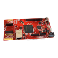
AURIX™ lite Kit V2
Hardware Description
Board Users Manual 14 Revision October, 2020
3 Configuration
3.1 Bootmode
Table 6 User Startup Modes
1)2)
Start-up mode is selected by Boot Mode Index
Internal Start from Flash
Alternate Boot Mode, Generic Bootstrap Loader on fail
(P14.0/P14.1)
Generic Bootstrap Loader (P14.0/P14.1)
1) The shadowed line indicates the default setting.
2) ‘A’ means assembled, ‘NA’ means not assembled, ’x’ represents the don’t care state.
Please see also Table 8.
3.2 Config Signals
Table 7 Config Signals
Only with TC2X5, resistor R30 (4.7 kΩ/0603
imp) pulls signal against GND (DCDC) and is
assembled initially if board is using TC2X5.
HWCFG1 (EVR33ON / EVR33OFF)
Resistor R31 (4.7 kΩ/0603 imp) pulls signal
against GND (EVR33OFF) and is assembled
initially.
HWCFG2 (EVRCON / EVRCOFF)
Resistor R52 (4.7 kΩ/0603 imp) must be
assembled if R59 is assembled (GPIOs are set
to tri-state) and TC2X5 is used (TC3X5 has
internal pull-up).
HWCFG3 (see boot configuration Table 6)
HWCFG4 (see boot configuration Table 6)
HWCFG5 (see boot configuration Table 6)
HWCFG6 (GPIOs pull-up / tri-state)
Resistor R59 (4.7 kΩ/0603 imp) pulls signal
against GND (GPIOs in tri-state after reset) and
and is not assembled initially.

 Loading...