AURIX™ lite Kit V2
Table of Contents
Board Users Manual 5 Revision October, 2020
List of Figures
Figure 1 Block Diagram of the AURIX™ lite Kit V2 ............................................................................................. 7
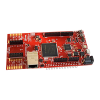
Figure 2 AURIX™ lite Kit Board V2 View from the Top ....................................................................................... 8
Figure 3 AURIX™ lite Kit Board V2 View from the Bottom ................................................................................ 8
Figure 4 Power Supply Concept ....................................................................................................................... 10
Figure 5 Signal mapping of the pin headers X1 and X2 ................................................................................... 16
Figure 6 Signal mapping of the pin headers for Mikrobus and Shield2Go Connector 1 and 2 ........................ 17
Figure 7 Mapping of Arduino Functions to AURIX™ Pin Functions .................................................................. 18
Figure 8 Schematic: Project Overview ............................................................................................................. 20
Figure 9 Schematic: On Board miniWiggler ..................................................................................................... 21
Figure 10 Schematic: Power and Connectors .................................................................................................... 22
Figure 11 Schematic: CPU and config ................................................................................................................ 23
Figure 12 Schematic: Ethernet and memory expansion .................................................................................... 24
Figure 13 Placement: Top View ......................................................................................................................... 25
Figure 14 Placement: Bottom View ................................................................................................................... 26
List of Tables
Table 1 Overview of the Board Specification ................................................................................................... 6
Table 2 AURIX™ Pin Mapping for User LEDs .................................................................................................. 10
Table 3 miniWiggler Pin Mapping for User LEDs ........................................................................................... 11
Table 4 AURIX™ Push Buttons and Potentiometer ........................................................................................ 11
Table 5 CAN Signals and AURIX™ Pin Mapping.............................................................................................. 12
Table 6 User Startup Modes ......................................................................................................................... 14
Table 7 Config Signals .................................................................................................................................... 14
Table 8 Signal mapping of the optional resistors .......................................................................................... 15
Table 9 Pin Assignment of the DAP Debug Connector .................................................................................. 19
 Loading...


