3.13.5.4 Drawings S1 and S2 mean the bypass input acceptable window, it can be
184Vac~260Vac or 195Vac~260Vac.
3.13.5.5 Drawing T means the bypass frequency window of the Inverter Output, the
acceptable setting values are ±3Hz and ±1Hz.
3.13.5.6 Drawing U means the acceptable Inverter Output Voltage, of which
voltage is 200Vac, 208Vac, 220Vac, 230Vac, or 240Vac.
3.13.5.7 Drawing V1, V2, V3 and V4 mean the operation modes of the UPS, of
which alternative is Online, Eco(Economic) mode, fixed 50Hz Output or fixed
60Hz Output.
3.13.5.8 Drawing W means the adjustments of the Inverter Output, which may be
calibrated as 0%, +1%, -1%, +2%, -2%, +3%, or -3%.
3.13.5.9 Drawing X means a specified address & position of the UPS when the
UPS is in Parallel mode. The settable numbers are from 1st to 4th. The
number must be 1
st
if the UPS is not in parallel.
3.13.5.10 Drawing Y means the parallel function status. The “P 01” means parallel
function disabled and the “P02” means parallel function enabled.
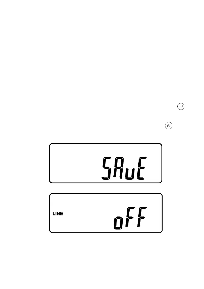
3.13.5.11 When all the setting changes are done, you have to press enter key
Pad to save all the changes when the LCD screen shows as drawing Z, then,
the LCD screen will show as drawing AA to complete the setting changes. If
you don’t want to change those settings, you may press “OFF” key pads
for 5 seconds, then the LCD screen turns to Drawing AA directly, which means
your setting changes are invalid.
Z
* Please press Enter key to save data.
AA
* It shows the UPS is locked.
3.13.5.12 Turn Off the breaker of Utility Input.
3.13.5.13 Your Setting changes are complete.